
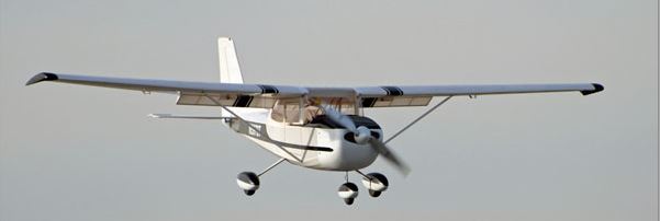
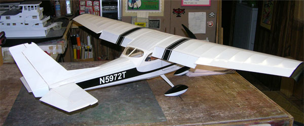
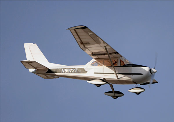
The Cessna 172 is considered the most successful light plane ever built. We have a complete Construction article for this icon of civilian aviation in the May issue of MAN and so we wanted to show off a little.
Designed by Pat Tritle, this classic Cessna has trike gear and working flaps. And like all of Pat’s designs, it is easy to build and it flies great. Check it out.
To order this 3-page plan set ahead of time, CLICK HERE.

The Model
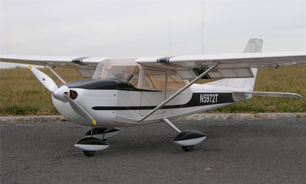
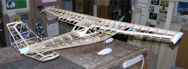
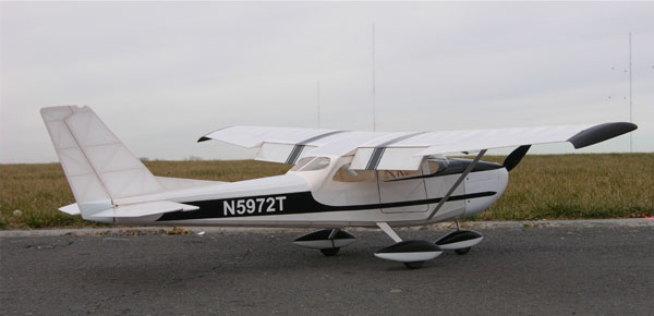
My model is 1/8-scale and has a 53.5-inch wingspan. It utilizes conventional stick and tissue fuselage and tail group construction and easy to assemble egg-crate construction for the wing makes assembly quick, strong, and light. Though not an overly-large model, the plug-in wing panels are removable for easy transport and are held in place by magnets so no tools are required to take the model apart.
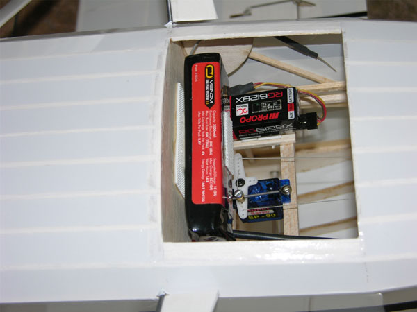
The battery and radio gear is easily accessed through a removable hatch on the bottom of the fuselage. And to make things simpler, a laser cut wood and plastic parts package is available from manzanolaser.com for those who would prefer not cut their own parts. The C-172 is set up for 5-channel RC control using six sub-micro servos that include the standard flight controls plus functional flaps making it the perfect candidate for smaller flying fields due to its slow and gentle flying qualities and short-field takeoff and landing capability. Power is provided by a low cost Outrunner motor and a 2-cell Lipo battery providing flight times in excess of 15 minutes.

Building the Model
Construction begins with the vertical and horizontal stabilizers building them directly over the plans. Because the stabilizers have an airfoil shape, shims are used to center the leading and trailing edges on the ribs. Fit and glue blue foam or light balsa blocks to the bottom of the rudder and sand to shape. The rudder and elevator are hinged using 5/32 x 1/2-inch strips of light CA hinge material. The hinges aren’t glued in place until after the frames have been covered.
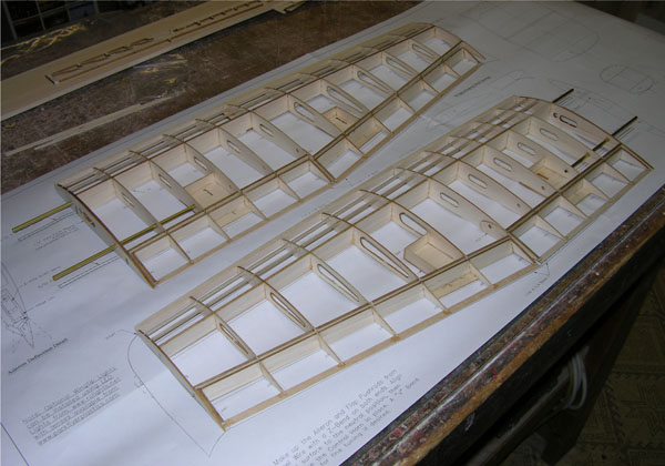
Wing Assembly
Begin by pinning SM1(servo plate), in place over the plan. Dry-fit all of the ribs onto the main and rear spars over the plan and pin the assembly in place using the Washout Jig under R9 to support the outer ends of the spars. Glue each point of contact followed by the leading edge. Build the flaps and ailerons in place along the wing assembly over the plans, then remove the assembly from the board and add the aileron servo and strut mounts and sand the assembly to shape. Hinge the flaps and ailerons as described in the stabilizer assembly. Cut and fit the brass joiner tubes to length and glue them in place. And finally, glue the flap and aileron servos in place using silicone caulk and run the servo wiring out through the root rib. Make up the wingtip blocks from blue foam or soft balsa, glue R9WT rib in place, and carve the tips to shape using the provided detail drawing. Glue the tips in place on the wing assembly.
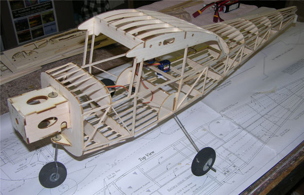
Fuselage Assembly
Start by building the side frames over the assembly drawing. Remove the frames from the board, align and glue the B2 (landing gear mounts), in place on the inside of the left and right hand side frames. Bend the landing gear to shape and glue it into the former assembly (4A/4B/4A). Join the frames beginning with the upper cabin formers and landing gear assembly taking extra care to insure that the assembly is square. Then add the remaining formers to complete the basic assembly.
Fit and glue the servo mounts in place, install the servos and install the elevator pushrod tube and rudder pull/pull cables. Build up the motor mount assembly and glue it in place. Bend the nose gear strut wire to shape, build up the control horn and assemble the nose gear into the overall mount assembly. Connect the pushrod to the servo arm using a Du-Bro EZ-Connector. Now that everything is in place, add all of the top and bottom stringers and sand the fuselage assembly to final shape. Install the motor and ESC and run the power leads into the fuselage, then make the cabin fairings from Manila File Folder paper and glue them in place to complete the fuselage assembly.
Build up the lift struts as shown in the provided detail drawings. Sand the struts to an airfoil shape, then fit and glue the lower retention clips in place. Plug the wings into the fuselage and hand fit the struts, and then secure the outer retention clips to the struts.
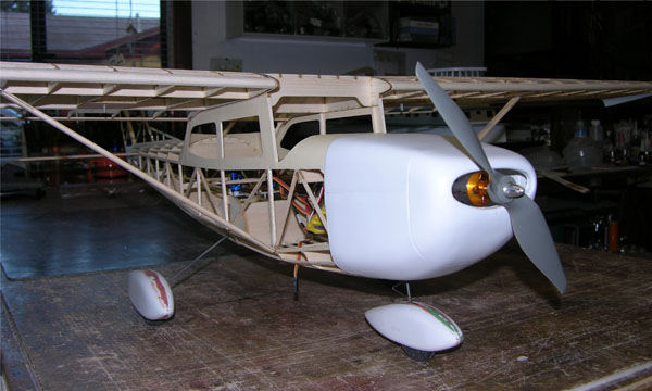
Assembling the Plastic Parts
Build the cowling and wheel pants and fit them onto the fuselage assembly, but don’t glue them in place until after final assembly. If you’re new to assembling plastic wheel pants you can go to my how-to webpage at patscustom-models/wheelpants.html for a complete tutorial. Assemble the cowling, trim as needed and fit it to the fuselage with the motor in place then secure it with the mounting screws left over from the flap and aileron servos. Build the battery hatch from balsa and styrene using the detail drawing provided.
Covering
Any of the light weight iron-on coverings such as Microlite or Coverlite are well suited to these light structures. Before you begin covering, disassemble the model and do a final detail sanding to prep the assemblies for cover. Then apply the covering material per the manufacturer’s recommendations and add any desired paint and trim scheme. Make up all of the cabin windows from clear acetate sheet. The windows can be glued in either on the inside of the paper fairings or on the outside. However, fitting them on the inside produces a much nicer looking finished model. If you opt for the inside, start at the rear of the cabin and work your way forward to the windshield.
Final Assembly
Glue all of the hinges in place using white glue such as Zap Formula 560 Canopy glue. Plug the wing panels into the fuselage and attach the lift struts. Remove the hatched section of Former 11 and slip the horizontal stabilizer into the mount. Using the wing for reference, align and glue the stabilizer in place. Align and glue the vertical tail in place, again using the wing for reference. Install the elevator pushrod through the cutout in the firewall and secure it to the servo arm with a Z-bend. Then make another Z-bend at the stabilizer hinge line, align the elevator in the neutral position and glue the control horn in place.
Install the rudder cables using the provided diagram. Run the cables into the fuselage and tie them off to the control horn. Test the system to insure the rudder and nose wheel both move in the same direction. If they’re not, swap sides by crossing the rudder cables – that’ll be a lot easier then changing the nose wheel linkage. When everything is functioning properly, secure the cables to the control horn.
Make up the aileron control rods from .032-inch diameter steel wire. Make a Z-bend on one end and slip it onto the servo arm. Make a Z-bend at the hinge line, align the aileron to the neutral position and glue the control horn in place. To set up the flaps, position the servos to the full up position, and then follow the same procedure as the ailerons to fit the pushrods. Set the controls for the throws called out for on the plans. The flaps will require a bit of elevator trim correction, so mix in a little down trim at half and at full deflections. The final set up will be adjusted as needed when the model is flown. Then with the flaps in the up position, make up the .010-inch thick styrene flap gap fairings and glue them in place on the top of the wing. Install the wheels and pants and re-install the nose wheel into the motor mount box. Attach the cowling and add any desired details to complete the model.
Balance the model 2.3-inches from the wing leading edge at the root rib using the battery to your best advantage. My model has been flown with a 2000mAh 2S Lipo battery and balanced correctly with the battery mounted on the back side of former 4A/4B/4A. The battery is secured to the former with some Velcro fastener. And with that done, the Skyhawk is ready to fly.
In the Air
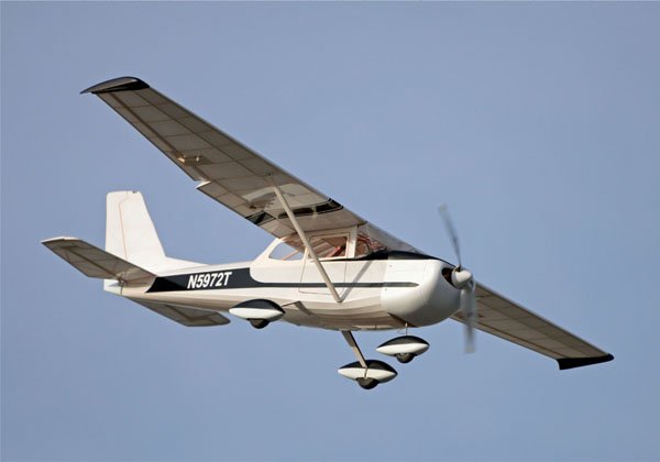
Though not a trainer, the Skyhawk is gentle, docile, and very easy to fly. Control is crisp and responsive, but not the least bit twitchy when set up as shown on my plans. Power is more then adequate, but the model is not over-powered, though rarely does the throttle need to go much past half. The flaps are very effective in slowing the model for landings, and when takeoffs are done at half flaps, the roll-out is quite short. Takeoffs can also be done with full flaps, but due to the added lift, be prepared to push in a bit of down elevator during the climb out.
Before your first flight, double check the controls to insure proper throw and direction of travel. To take off, slowly advance the throttle until the model light on its gear then lift off with just a touch of up elevator. Keep the climb shallow, and when at a safe altitude trim the model for straight and level flight with a comfortable cruise speed. To check the flap/elevator trim, slow the model down a bit and pull the flaps down to the takeoff setting. If the model pitches up, more down trim is needed. If it pitches down, some trim correction will need to be removed. Once the takeoff settings are determined, try slowing the model a bit more and go to the landing flap setting where the same trim setup will apply.
Landing without flaps is not a problem, but the model will land more slowly with half flaps, and even slower yet using full flaps. Try a few stalls at altitude at both flap settings to see how the model handles in slow flight, and once you get a feel for it, you can start experimenting with full and half flap landings. But where the model really shines is with touch-n-go landings. Fly the approach with full flaps, and when the mains touch down, go to half flaps, power up and you’re off and running again. But above all, enjoy the ride
To see the latest plans available at the AirAgeStore.com website, CLICK HERE
Specifications:
Model: Cessna 172
Type: Sport-scale
Scale: 1/8
Wingspan: 53.5 in.
Length: 38.75 in.
Weight: 25.6 oz.
Wing Area: 390 sq. in.
Wing Loading: 6.9 oz./sq. ft.
Gear Used
Radio: JR XG8 Transmitter w/JR RG612BX receiver (jramerica.com)
Motor: Suppo 2217/9 outrunner (altitudehobbies.com)
Servos: 6 E-Flite S-75 or similar (horizonhobby.com)
ESC: 20A w/3A BEC (e-fliterc.com)
Propeller: APC 11-5.5E (apcprop.com
Battery: Venom 2000mAh 2S Lipo (venompower.com)
S/B-Materials List:
Balsa and Ply Sheets Required for Scratch Built Model only
2- 1/16 x 4 x 36 Balsa Sheet
1- 3/32 x 4 x 36 Balsa Sheet
3- 1/8 x 4 x 36 Balsa Sheet
1- 1/32 x 3 x 8 Ply
1- 1/8 x 3.5 x 13 Lite Ply
3- 1/16 Sq. x 36 Balsa
7- 1/16 x 1/8 x 36 Balsa
3- 1/16 x 3/16 x 36 Balsa
2- 1/16 x 1/4 x 36 Balsa
18- 3/32 Sq. x 36 Balsa
1- 3/32 x 1/4 x 36 Balsa
8- 1/8 Sq. x 36 Balsa
2- 1/8 x 3/16 x 36 Balsa
1- 3/16 x 1/2 x 36 Balsa
2- 3/16 Sq. x 36 Balsa
2- 1/4 x 3/8 x 36 Balsa
Blue Foam or Balsa Block (Wingtips and Rudder Fairing)
1- .025 dia. x 36 Steel Wire
1- .032 x dia. 36 Steel Wire
1- .046 x 36 dia. Steel Wire
1- .093 x 36 dia. Steel Wire
1- 5/32 O. D. x 36 Brass Tube
1- 3/16 O. D. x 36 Aluminum Tube
1- .032 x 1/4 x 2 Brass Strap
1- 2-inch Nose Wheel
1 Pr.- 2 1/4-inch Main Wheels
3- 3/32 Wheel Collars
1.5 Rolls- Microlite
1- .010 x 6 x 12 White Styrene
2- .008 x 6 x 12 Acetate
2- Servo Y-Leads
2- 6-inch Servo Extensions
2- 9-inch Servo Extensions
1- Micro EZ-Connector
Plans Blurb
Cessna 172 | X0517A
Designed by Pat Tritle, this 1/8-scale Cessna 172 is easy to build and uses conventional stick and former construction and egg-crate wing assembly. It is lightweight and flies great. The model has a steerable nose wheel and functional flaps. Laser cut and formed plastic parts are available.
Span: 53.5 in.; Power: Suppo 2217/9 outrunner; Radio: 5-channel; LD: 2; 3 sheets; $27.95


Hur mycket kostar den Cessna 172?