Building a wing:
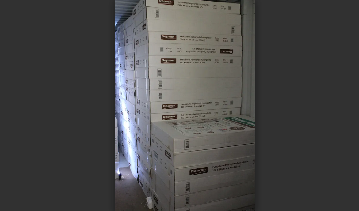
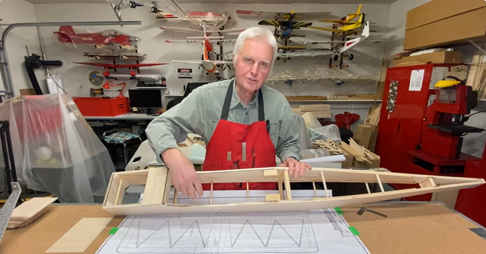
The plans for this model were hand drawn by Ivan Pettigrew. A well know and respected designer. They were somewhat rough in nature but did allow for very easy modifications. All the drawings were on a single sheet so it was necessary to cut each section from the main plan sheet in order to simplify the build process.
You should always cover your plans with a clear wrap or other translucent material to avoid gluing your model to the plans or build surface. As with all scratch builds, you need to cut out patterns from the plan sheet then trace the patters on to the flat sheet stock material. For the wing. cut all of the formers out first. Match each former to its corresponding former for both wing halves. This will insure both wings are the same when completed. I have found a single sided razor blade works best for this. You can get these at your local hardware store. A box of 100 blades cost around$7.00-$9.00
Test fit all the formers over your plans on the main spar prior to gluing. Some adjustments may be necessary so text fit all components first. Use a straight edge to help align the formers to insure a tight fit with the back of the leading edge material and the front edge of the formers.
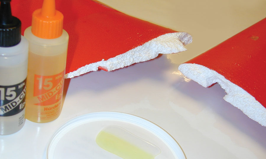
Once you are satisfied with the fit. Glue all the formers except former one (center former) to the main spar using a square to insure the formers are perpendicular (90 degree angle) to the build. Most wings are designed with dihedral. The number one former(s) (center former) may need to be place at an angle relative to the build surface. Consult the plans and if necessary, create an angle piece (jig) that is appropriate for your model. Use this angle jig to position the center former at the appropriate angle. This model has 2-inches of dihedral. Requiring the center former(s) be placed at an angel. Make certain that all formers on aligned properly over the corresponding locations on the plans. For gluing formers to the main spar I recommend using Medium CA glue. An accelerator may be used but is generally not necessary.
Most sets of plans don’t provide the order in which you should build different components. This is up to the builder. I usually build the flight surfaces along with the wing to insure a good fit. As you can see below. This was done for both the ailerons and flaps. The plans for this model didn’t have the flaps drawn but I felt they would be very advantageous given the tapered wing design. The flaps I designed deploy between the nacelles and the fuse. This design creates less drag and extends the wing surface affording slower landing speeds. It was only later. After I had completed this build that I learned the original style of flap used on the full size Comet. The original flaps were more of an air brake design. A one piece flap running between the nacelles and under the fuselage. For scale effect I should have done my home work. Oh well better with flaps than without.
 |
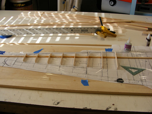
| Notice the wing extends straight on the plans. |
Sheeting the flight surfaces once their sub structure is complete makes them much easier to work with and you are less likely to cause damage due to rough handling. Do this as soon as your flight sub structures are completed.

The photo above shows the flap with the bottom sheeting applied.
The photo below is the aileron with the bottom sheeting applied.

The picture below shows the wing with the bottom sheeting applied. The wings design is asymmetrical. This was a great time to stabilize all the formers and insure a good fit with the aileron and flap components. Do not sheet the top of the wings till after the wings are joined. A wing joiner is used and must be installed between the to wing halves on the main spars prior to top sheeting the wing. The picture also shows the leading edge and upper spar installed. It’s important to install these pieces prior to sheeting the bottom of the wing. Once the sheeting is installed the wing will become very rigid. Make certain there are no twists in the wing prior to gluing the sheeting in place. Secure the wing flat on your build board prior to gluing the sheeting in place. You can choose to create holes in the formers for servo wiring prior to gluing the formes to the main spar or after the formers are attached and the bottom sheeting is applied.
A 1/2-inch outside diameter piece of aluminum tubing at least a foot long makes a great boring tool for this purpose. Place the 1-ft aluminum tube in a vise and rough up the end with a hack saw to create a cutting surface. Place the cutting end of the tube against the former and rotate back and forth in a drill like manner. This will produce a nice clean hole for your wiring to slide through. All the holes will line up perfectly using this method. Work your way through as many formers as needed to reach the farthest servo location.
Just don’t forget to make these holes before the top sheeting is applied or you won’t be able to feed your servo wires through the wing.

You will notice, long wing formers were created for the center section. This is a deviation from the original plans. The plans call for the center wing extender sections (fillets) to be attached to the fuselage. If you have ever tried to get the fillets of any size to be flush between the wing and the fuse you know the challenges involved. I elected to make the center extension section a part of the wing. The plans also indicate the wing will be permanently attached to the fuselage. I prefer a removable wing configuration for ease of transport and repairs as needed.
Note: See photo of the plans above. Notice that the wing drawing shows the trailing edge of the wing extending straight to the fuse.
This modification makes removing the wing very easy and accelerated the build considerably. Smaller wing fillets were built and attached to the fuse for a smooth scale transition. Two other deviations were incorporated. The first is the use of 3/32 balsa flat stock for the wing formers rather than the 1/16 balsa material indicated on the plans. The 3/32 balsa material was much easier to work with and far less fragile. Secondly, I prefer a fully sheeted wing. Sheeting the wing adds a great deal of strength while creating a sooth scale appearance. Ivan Pettigrew designed this model to be very light. Although these modifications added weight to the model. The over all finish justified the alterations. You be the judge.

I have mentioned before that I prefer ease of operation and access to components within the model. I took a note from ARF’s I’ve assembled and incorporated access doors for the servo(s). The best way to create these doors is while the wing is still on the built board. Measure and cut the doors before cutting out any sheeting on the wing. I recommend using 2/32 light ply for your access doors. If you like, you may want to laminate 1/16 sheeting to the outer surface of the doors. This is helpful when doing the final sand on the wing. The doors will have the same surface density as the surrounding wing and will sand flush much easier.
Once the doors are the desired size and fit snug between the formers. Use the doors as a template to draw the pattern on the inside of the wing sheeting. Cut out the door patterns from the inside of the wing. Stay inside the pattern lines or your opening will be too large. Install mounting rails or other material for the access doors to attach to. Place the doors in the appropriate openings and pre drill the holes for the mounting screws. Mark each door with its location and indicate which edge faces forward. This will insure a good fit later. Using a servo as a guide, mark the opening for the servo arm and mounting blocks. Cut out the servo arm opening. Epoxy the servo mounting blocks in place. Doing all of this before applying covering insures all your parts fit well and no epoxy gets on the covering. Temporally mount the servo to your servo door and test fit in the opening to insure there will be no interference. Install mounting screws and snug them down. If your satisfied with the fit, remove the doors and detach the servo(s).
Build the other half of the wing in the same manner and to the same point of completion.
Once you have both wing halves completed. It’s time to join the wing halves together. First test fit to insure proper fit and alignment. Place one wing halve flat on your build surface and secure in place. Place the other wing halve in position and support the outer wing with a block of balsa or a wing jig if you happen to have one. Use small clamps to hold the wing halves together. If the fit is good remove the clamps and lift the unsecured wing off the build surface. Apply epoxy to both inner wing formers and to the wing spars were the wing joiner will attach. Place the wing half back in position and clamp in place. Install the wing joiner and clamp in place. Let the epoxy cure over night.
You may now sheet the top of the wing. Place the wing back in the build surface and secure one side in place. This will be the side to be sheeted first.
Laminate the stock sheeting material being used together prior to attaching to the wing formers. Sand smooth after gluing. Cut the sheeting material to the proper shape but slightly oversize. This will allow for slight adjustments as may be needed for proper fit. Test fit your material prior to gluing and make any adjustments required. When you are satisfied, run beads of Medium CA glue on all the surfaces to be glued. Quickly place your sheeting on the wing and apply pressure to the entire surface. Move you hand over all the wing surface insuring contact between the formers and the sheeting is good. Once the glue has dried you may remove the wing from the build surface and inspect for any gaps at the glue joints. Apply additional glue if required. Sand off any excess material, but don’t sand the wing surfaces at this time. Repeat this process for the other wing half. You should now have a completed wing.
Do not finish sand the wing yet.
End Part II