
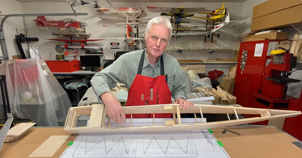
So, I finished up the dummy rotary engine for the Sopwith Camel this weekend. The over all project took only about 10 hours and spread over a few days, that’s no time at all. I finally decided to attach the molded engine to the inside of the engine cowling. This is the typical way to affixing it to a model, but if you have the room, you can also install standoffs to the firewall around the G38 and attach the dummy rotary that way. Here’s how I did it.
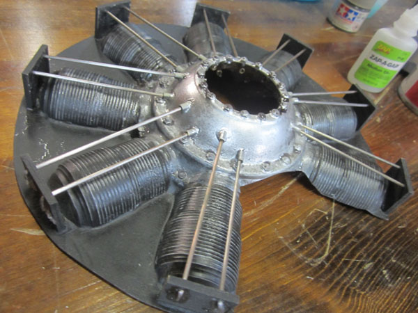
This is where we left off in Part 2. Basically the dummy engine has been painted and detailed and was ready to install. You’ll notice the wood guide plates I installed above each cylinder. These both support the pushrod wire ends and, give excellent purchase points for the molding to be glued to the inside of the engine cowling.
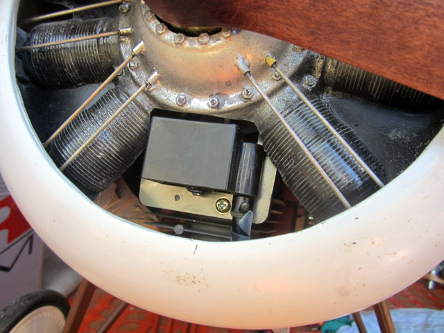
After sanding the paint off of the edges of the guide plates, set the dummy engine in position over the model’s real engine and then you reattach the engine cowling. Make sure the dummy engine is centered around the prop hub and that nothing comes in contact with the G38 when the propeller shaft is turned. Now tack glue a couple of the guide plates to the inside of the cowling using Thick Zap and kicker. Remember, before applying any glue, it is very important to clean off the inner surface of the cowling to ensure a strong glue bond. I use MEK to remove all the paint and primer from the inner surface of the fiberglass cowling.
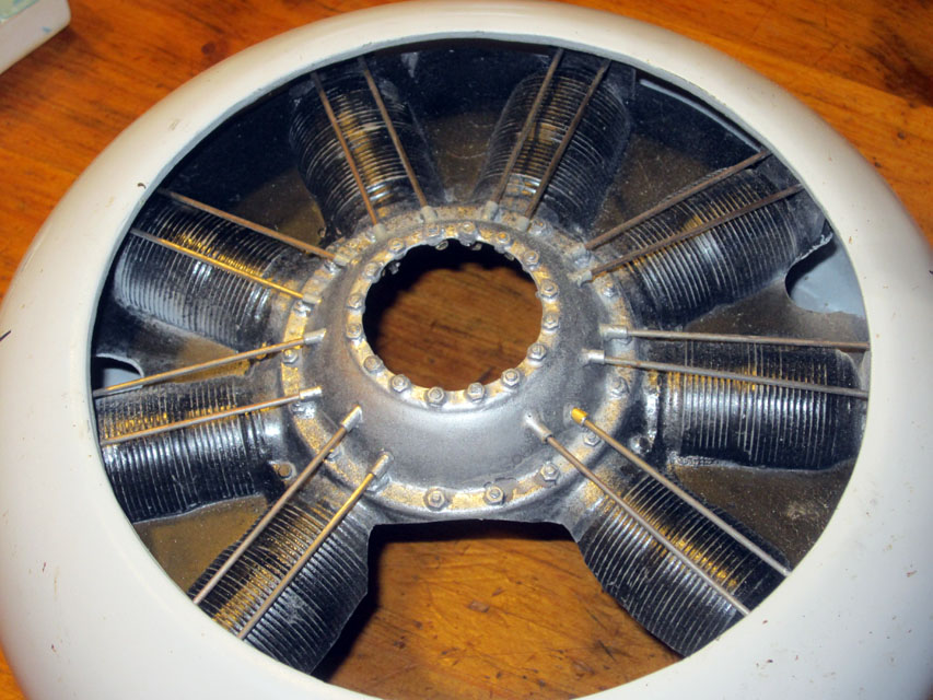
After the glue sets, tack glue a couple more plates to the inside of the cowling. Once you have three or four plates glued in place, you can remove the cowling.

Here’s a close up of one of the plates glued to the cowling. Finish gluing the rest of the guide plates in place being sure to build up a strong fillet around the guide plates.

After all the attachment points have been secured, be sure to make some openings in the webs between the cylinders. These are to get to any screws or other attachment points for securing your engine cowling in place.
All you need is an opening large enough to fit a screwdriver . With my magnetically secured cowling, I also installed two screws to prevent the cowling from rotating due to engine vibration. The screws go through the rear plywood cowling ring and thread into hard points in the front of the firewall.
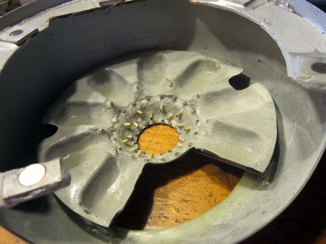
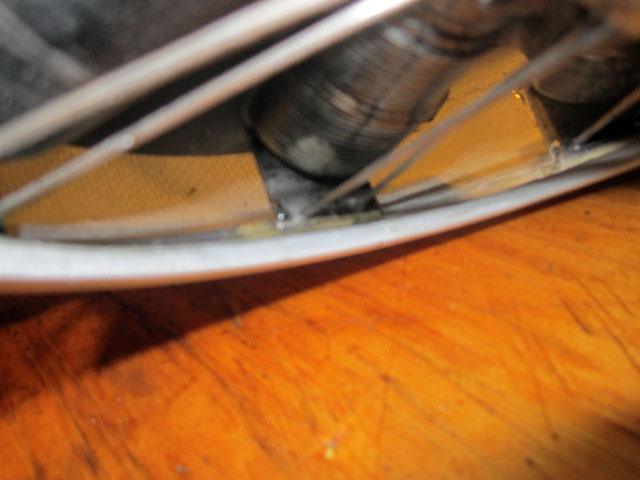
Here you see the backside of the dummy engine. Notice that there’s plenty of space around the dummy engine for airflow to cool the engine. Most of the airflow will be through the large opening just in front of the cylinder. Also if there is a gap between the cowling and any of the plates, (as shown here to the right), add a scrap of lite ply to fill in the space. Use plenty of Zap and kicker.
Reinstall the engine cowling and check the clearances around the model’s engine. Try to have at least 1/8 inch all around. When everything lines up properly, remove the engine one more time and give it a few light coats of honey colored clear Urethane spray finish. This will seal the wood guide plates and coat the pushrods so they don’t corrode. Also the color give the engine a semi wet look like it just ran and is covered with caster oil.
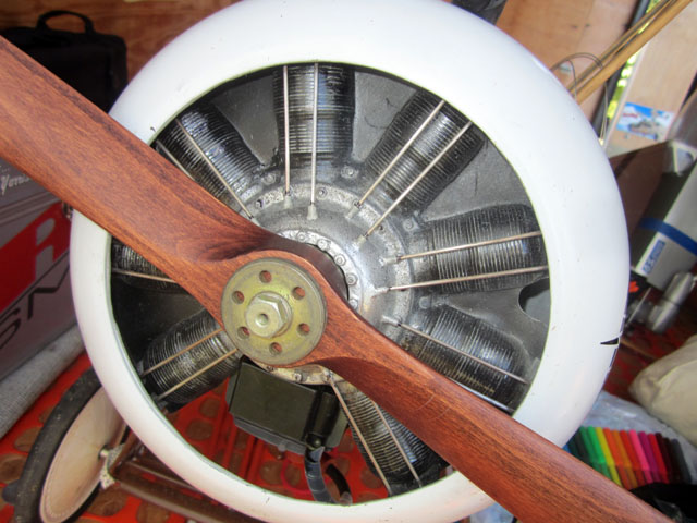
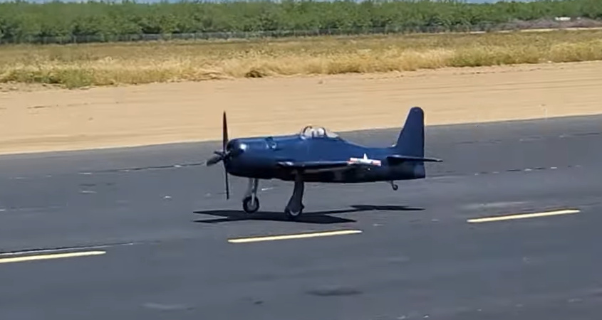
So, that’s it! The molded fiberglass dummy rotary engine from Balsa USA is an excellent starting point for any round nose airplane. It certainly is a lot less work than scratch building your own WW1 cover-up. After a couple of flight, check the clearances between the scale engine and the prop hub. If anything is rubbing, use a Dremel Moto-Tool and grind away any interference areas to increase the clearance. Also pay attention to how your engine runs. If it seems to be running hotter than without the scale engine in place, richen the top end a little. And recheck the idle transition. Have fun!
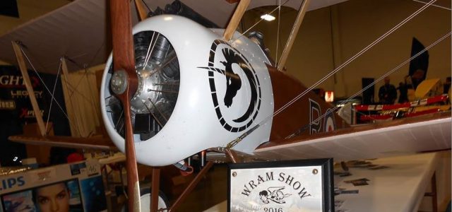
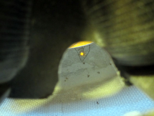
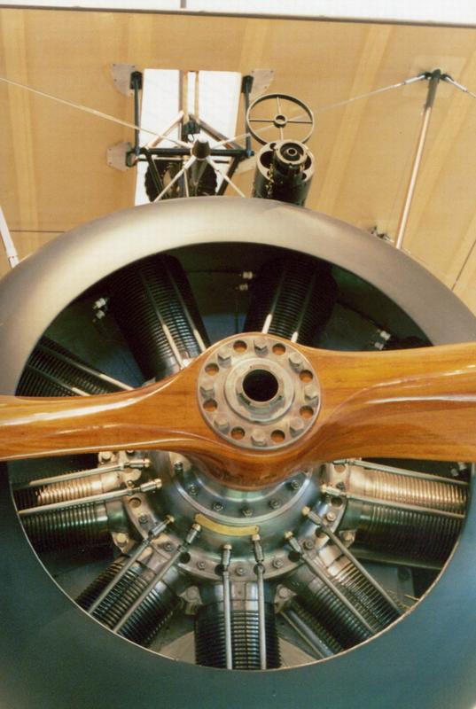
Here’s a reference photo of a Sopwith Camel rotary engine.


Gerry,
Very nice job on the dummy radial install ! I have done similar projects with my airplanes that have radial engines, Waco,Super Stearman, Stinson Reliant etc. But I cut out the panels between the cylinders to give the engine an even more scale look. To this point I have not had any problems with cooling. The exit area is also proportionate to the inlet area. 2:1 I would value your opinion on this type of installation as opposed to removing only the area around the cylinder head and leaving the rest of the webs intact.
Thanks much, Jim B.
Hi Jim. so far the Camel flies great without over-heating. With my setup, most of the engine cylinder head and the muffler are exposed under the fuselage. So with the single opening I use for air-flow is adequate. If you are using a more tightly cowled in engine, I too would open up most of the space between all the cylinders. And yes, the air-in to air-out ratio is 2:1. even 3:1 will work but then the opening in the fuselage get to be a bit more noticeable. cheers, GY