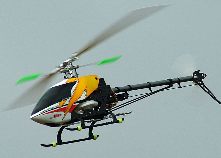
First flight test your helicopter with its standard tail rotor configuration, and note the gyro sensitivity setting as well as the tail rotor response on specific maneuvers. Now replace the stock tail rotor mounting bolt with a longer one so weights can be added to each side of the tail rotor blade. I have found that on a small electric helicopter, such as the Mini-Titan, a small ball added to each side of the tail rotor mounting bolt works well. For intermediate 50 size helicopters, try a large ball or 3mm flat nut, while on larger 90 size helicopters try an additional 4mm lock nut on each side of the tail rotor mounting bolt. Now again flight test your helicopter using the same maneuvers as you flew in the standard configuration and again evaluate the tail rotor response and the gyro sensitivity. If the tail rotor does appear to be more responsive, try adding a little more weight and again perform a flight test. If the tail rotor begins to flutter you have added too much weight. Even a small amount of weight should relieve much of the work load from the tail rotor servo, resulting in not only better tail rotor response, but reduced servo and battery requirements. You should also note the gyro sensitivity can be reduced to obtain the same holding power as in the stock configuration.
A more advanced test will let you feel the affects of the added CRM weight to the tail rotor. However, this requires starting the helicopter to bring the tail rotor up to speed, and then moving the tail rotor pushrod with your hand to evaluate the force required to position the tail rotor blades. For your safety, this test requires the helicopter be secured in position so it can’t move, and everything from the main shaft should be removed. There is also the possibility the added weight to the tail rotor could cause a blade grip to fail, causing the weight and tail rotor blade to separate from the tail rotor, so stay out of the plane of the tail rotor.
With the stock tail rotor, secure the helicopter in position, disconnect the tail rotor pushrod from the servo, and disconnect the servo arm so it won’t get in the way. If possible, have an assistant advance the throttle to bring the tail rotor up to a moderate speed and then push and pull slightly on the pushrod to evaluate the force required. Shut down the engine and add the CRM weights as mentioned above to an extended tail rotor mounting bolt and perform the experiment again. You should be able to feel a reduction in the force required to hold the tail rotor blades in a deflected position. Although you can vary the amount of CRM weight to suit your particular needs, I would recommend only enough weight to reduce the loads by about half.
A more advanced experiment requires the tail rotor pushrod to be disconnected at the tail rotor bellcrank, to allow the tail rotor blades to seek their own pitch. With the tail rotor in its stock configuration, bring the tail rotor up to speed. The aerodynamic forces should bring the rotor blades to their zero pitch, streamlined position. Now add the CRM weights mentioned above, and again with the tail rotor pushrod disconnected at the tail rotor bellcrank, advance the throttle and bring the tail rotor up to speed. If the CRM weights are within useable limits, the tail rotor blades will remain in their streamlined position. However, if the CRM weights are excessive, the tail rotor blades will go unstable and to their full pitch position. Adjust the CRM weights as needed to keep the tail rotor blades stable in their streamlined position with as much weight added as possible.
Conclusion – Each of us needs to determine if these CRM techniques will benefit the performance of our helicopter. If you are a novice pilot learning to hover and fly basic circuits, you will receive minimum benefits from implementing CRM since you are placing only moderate demands on your tail rotor system. However, if you are planning to fly more aggressively in the future, or would just like to have a better designed tail rotor, than CRM could be something to experiment with. But the greatest benefits from adapting CRM will be for those who fly aggressive 3D aerobatics and demand the maximum performance from their tail rotor.














Really good article- Could you measure the servo current to termine the same thing?
Bill Mowry bmowry@kanematsuusa.com