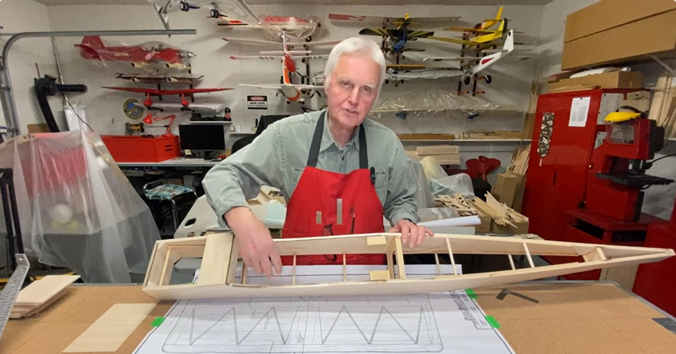
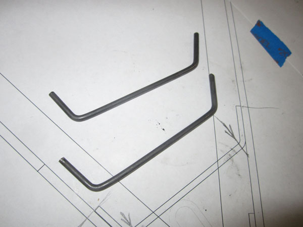
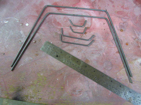
Now that the landing gear mounting blocks are installed in the fuselage, it’s time to switch to the landing gear itself. That is to check out the drawings and get the materials we’ll need to cut, bend and eventually solder the landing gear together. What I used is 3/16 inch Music Wire for the main struts (you could also use 5/32 inch if you like,) and I use 1/8 inch wire for the junction parts. These are the horizontal parts that give strength to the suspension section and join the front and rear strut wires together.
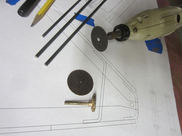
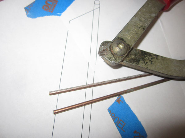
So for cutting the basic lengths of the wire, I print out the plan details full size, and estimate the lengths of the straight sections. I use tape wrapped around the wire and use a pen to mark the locations of the bends. For cutting, I use a reinforced cutoff disk and my Dremel Moto-Tool. When it comes to dressing the ends of the cut wire, I use a Robart Mfg., HD grinder disk.
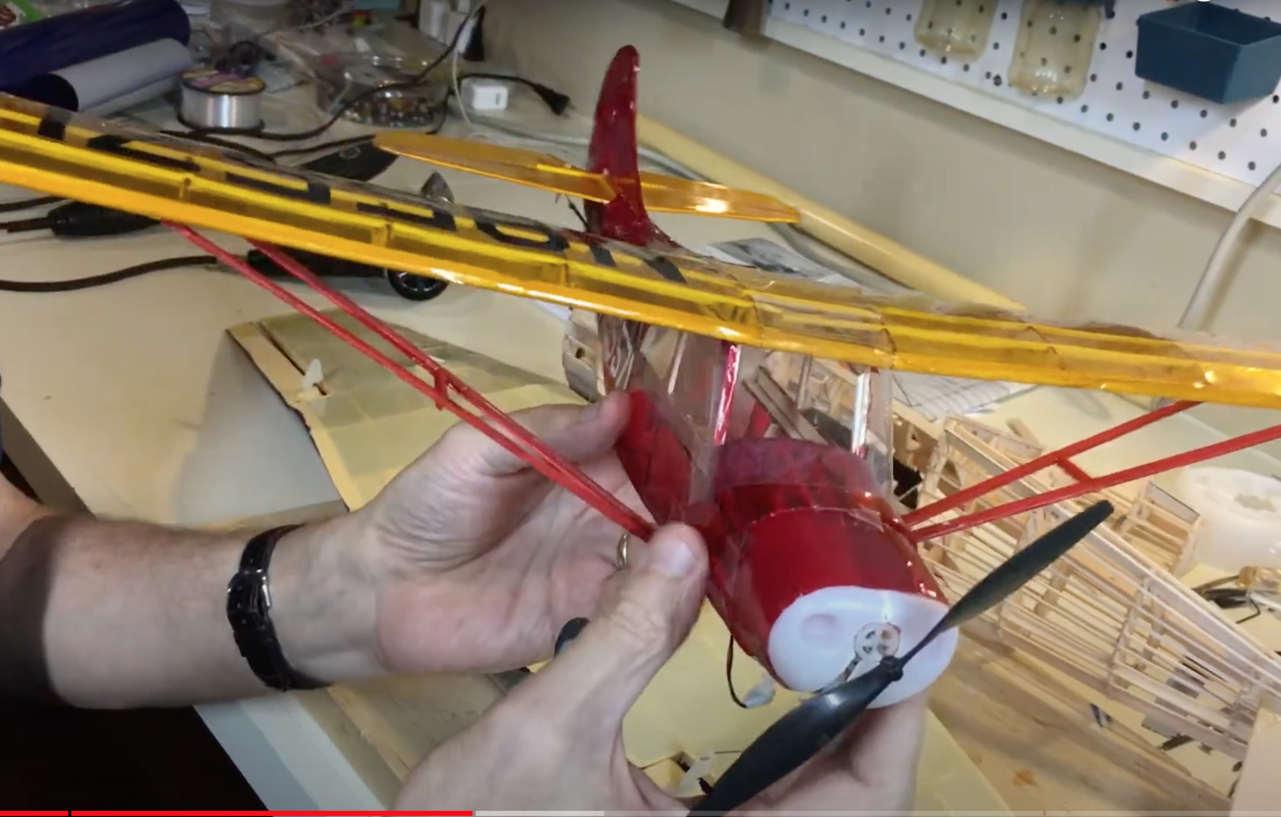
I am building a 1/4-scale Sopwith Camel and I have found that the size wire I am using is strong enough for my typical landings! If you are working wit a smaller model size, you can use 5/32 and 1/8 inch music wire. And if so, you may be able to use a wire cutter like below.
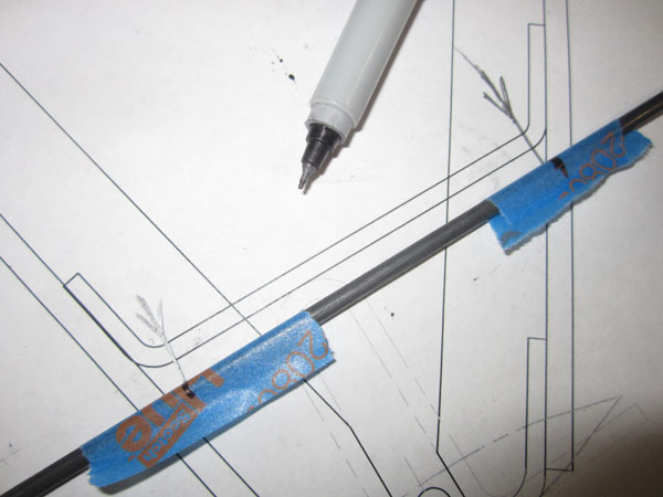
Typically I like to cut and bend all the smaller pieces first, but really it doesn’t really matter. So here the top cross piece is being formed. Adding tape to the wire makes it easy to see the bend lines. Notice that these are marked at the ends of the straight section. There is a radius at the two bends at the ends.
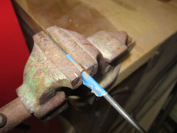
Align the bend mark on the edge of the bench vise with the wire placed horizontally, and then bend the wire. Here’s a tip. Place the short end in the vise, so you have increased leverage using the longer end of the wire. Always cut your wire extra long so you have extra material to work with.
Make the first bend (doesn’t matter which end,) and check the angle against your drawing. Once you have one end bent properly, check the position of the second bend mark and reinstall the wire and make the second bend.
The hard part really, is producing two pieces of wire, bent exactly the same way. Once you have this done, go ahead and cut the ends to length. Again, a little extra material comes in handy.
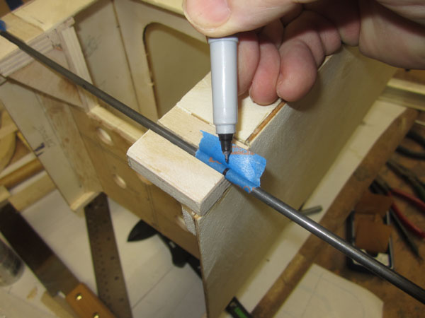
For the main landing gear wire struts, I take the length of the fuselage and transfer it to the wire as show. Once this cross-length is established, you can go ahead and place the wire in the bench vise.
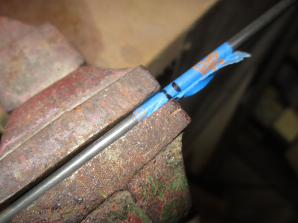
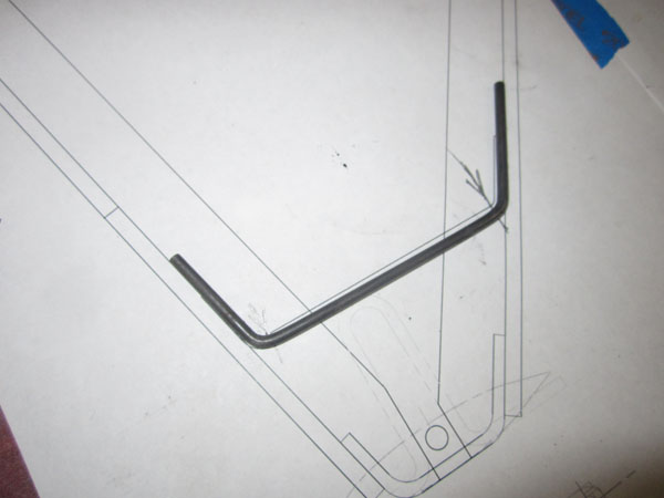
With the thicker 3/16 inch wire, I minimize the corner radius by setting back the bend line back by the diameter of the wire. This slightly shortens the cross length and sets the bend radius closer to the corner of the fuselage. Since the fuselage corners will be sanded and rounded a bit, it makes for a neater installation.
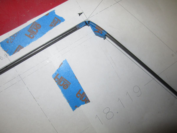
After bending the two ends of the wire at the set-back bend lines, I place the wire on the drawings showing the front view of the landing gear. There are two lengths for the wire struts, Typically, the aft gear strut is longer that the front. So make sure to mark you front and back parts. Placing each bent wire on the drawing also allows you to check that both left and right side bends are the same.
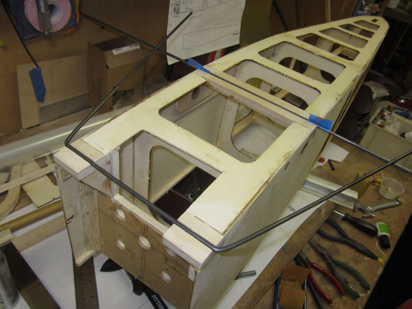
So here’s a little trick to check that both bent gear strut sections of the wire are at the same angle. Place a straight length of wire in one gear block and then place the bent gear wire in the other, here it is placed in the front blocks. Lower the bent wire down until the wire rests in the other, straight length of wire. Both ends of the bent wire should rest evenly on the straight wire. You can tweak the bend angles by twisting the wire by hand. Now to the other gear strut wire.
So that’s it for forming the landing gear wire. Took about an hour and everything is properly bent to shape. Next step is to solder the main structure parts together. Stay tuned!
Remember good builds rely on good parts. For excellent laser cut parts check out Trillium Balsa (www.trilliumbalsa.com)
To see the next part of the series (Part 6,) click the link: https://www.modelairplanenews.com/blog/2014/06/23/workshop-build-alone-sopwith-camel-soldering-landing-gear/
To see the last part of the series (part 4,) click the link: https://www.modelairplanenews.com/blog/2014/04/14/workshop-build-along-scratch-building-a-sopwith-camel-part-4-landing-gear-blocks/