As we continue with the wing construction, a major part of the build is installing the retractable landing gear properly. Unlike an ARF where the gear would more or less drop right into place, with a plans built airplane, like the Ziroli Skyraider, you have to install the plywood support ribs and mount rails do the gear end up straight and square to the building board. Here’s the process for the Robart 148E gear I am using with my 85 inch version of the Ziroli Skyraider.
Tech Note: To shorten the video, I sped up the video. The actual transit time up and down for the Robart 148E retracts is about 10 seconds each way.

Before the wing was even built, I used the Robart 148E gear to check the fit over the plans. Since the plans were reduced 15%, there was no way to know if the gear’s frame would fit properly in width and depth without actually having the units on hand. As you can see here, the fit is tight, but everything does fit without major adjustments to the structure. The only thing that I needed to adjust was the width between the two plywood support ribs W6-A and W6-B.
Knowing this ahead of time, I want ahead and built the left and right wing panels, but did not sheet them. This allows the fine tuning of the support ribs.

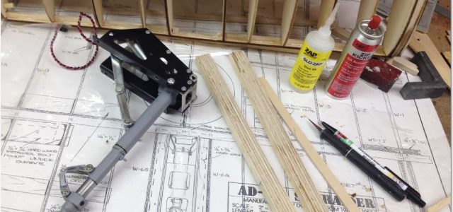
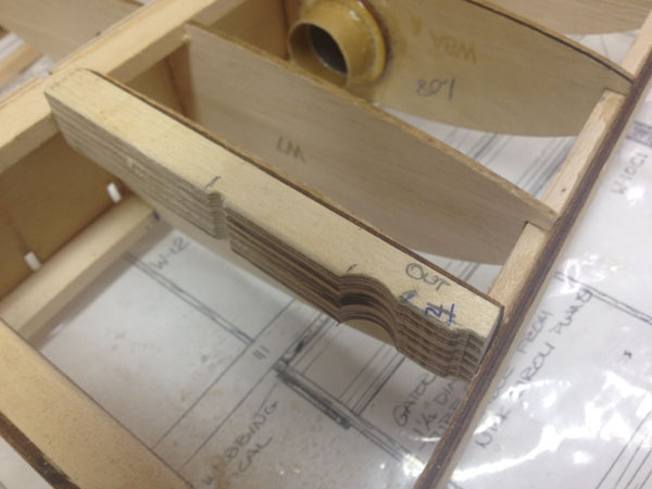
Here are the plywood landing gear support ribs and the laminated plywood rails that will support the gear.
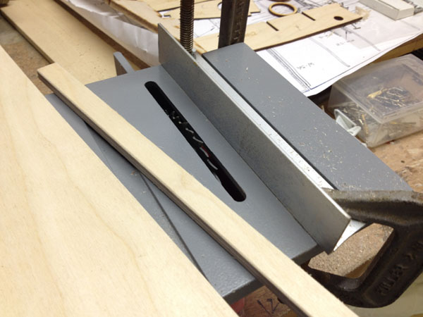
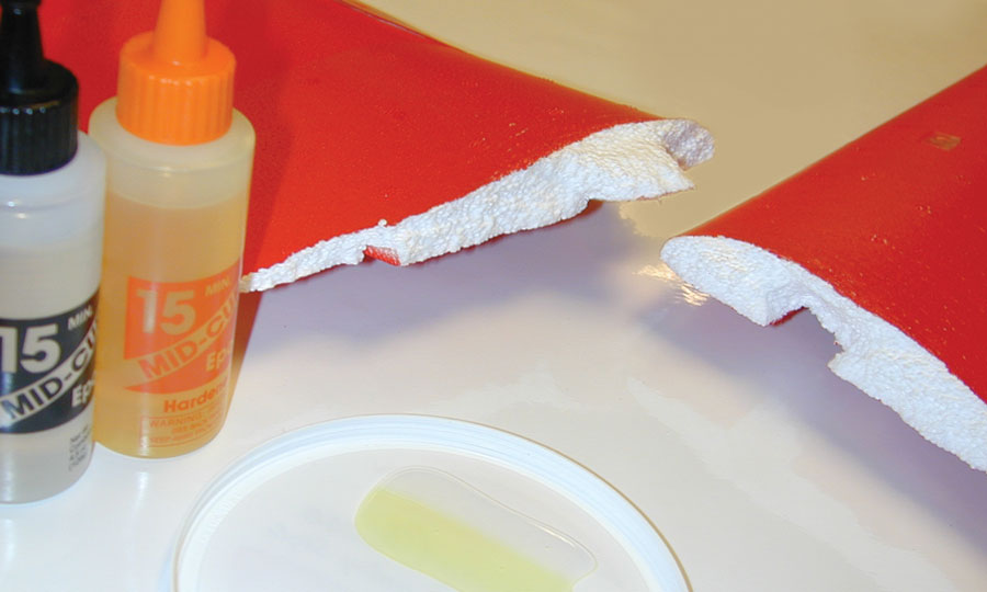
The easiest way I have found to make laminated plywood rails is to use a micro/hobby tablesaw to ripe the plywood, which in this case is 1/4 inch thick. Since the plans indicate the need for 1/2×3/4-inch rails, I ripped 1/2 inch strips so I could stack three together to produce the required depth.
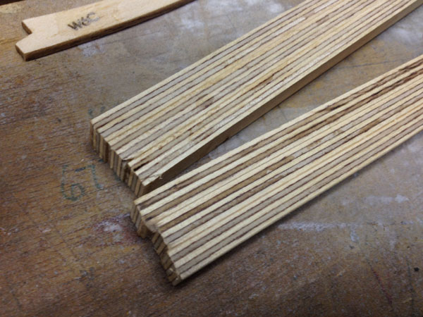
Here are the laminated rails ready to be cut to length. I used 15-minute Zap Z-Poxy to glued the strips together.
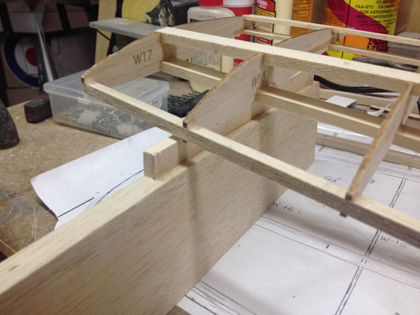
Since the W1 and W2 wing ribs have alignment/building tabs on them to keep them properly aligned with the building board, I used a 1/2 inch shim to lift the ribs off of the tabs, then I lifted the wing tip to the proper dihedral height above the building board.
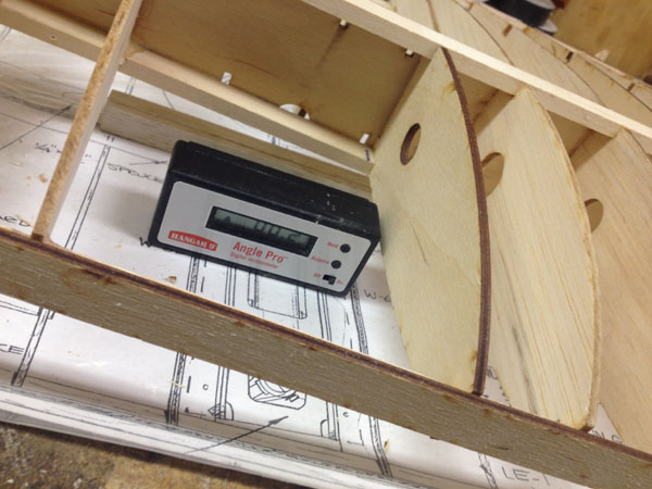
I next zeroed out my digital level/gauge on the building board. Then I fitted the inboard plywood gear support rib into place, but did not glue it into place. As you can see, because of the actual dimensions of the 148E gear, (centered on the gear location shown on the plans), the rib doesn’t key into the alignment notches in the plywood support web. I cut the tabs off the back of the rib and slide it into place.
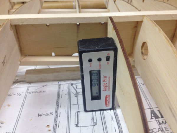
After checking the dihedral angle again, I then used the level gauge to position the inboard rib square (90 degrees), to the building board. I also used a square triangle to make sure the rib was square to the plywood web and the main spar.
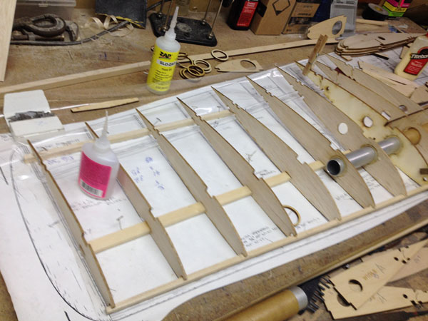
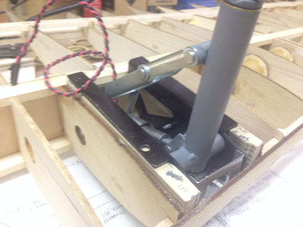
After lightly tack gluing the inboard rib into place, I used the landing gear unit and the two support rails as a spacer to determine the position of the outboard rib. The gear fits perfectly between the main spar and the plywood leading edge doubler. With the gear in place, I lightly tack glued the outboard rib into place making sure it too was square to the main spar. The 1/4-inch square balsa LE strip was cut away to clear the front of the gear frame.
For the gear frame to sit flat on top of the support rails, some trimming has to be done, to clear the pivot bolt and some of the screw heads. I did this with a dremel tool and a grinding bit. Also I sanded a light radius on the inner upper rail corner edges.

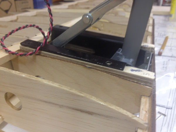
Here the two rails have been tack glued in place to check the alignment of the gear.
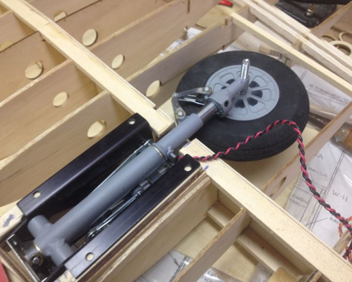
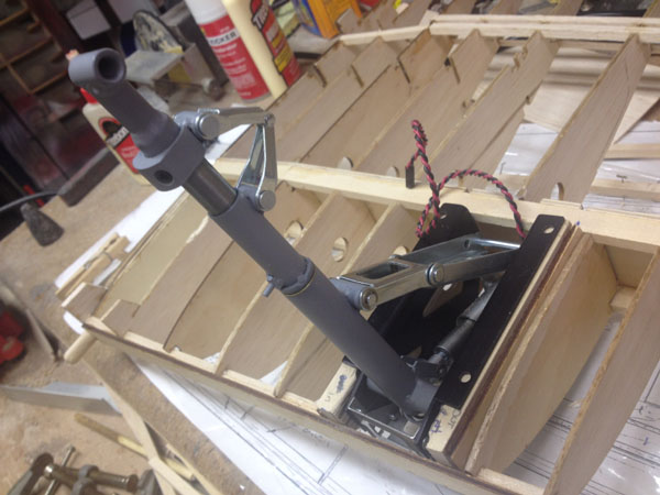
With the gear in the retracted position, I could also check the clearance of the strut and the wheel to the main spar. A small portion of the lower spar has to be cut away to clear the strut. With everything lined up, I cycled the gear up and down a couple of times to make sure the drive mechanism also clears the wing structures.
The plans show the support rails being glued flush with the bottoms of the plywood ribs, but with my reduced wing dimensions, I had to position the rails about 1/8 inch proud of the rib bottoms. This was so the top of the gear frame would clear the wing’s top sheeting.
So basically that its for now. I won’t permanently epoxy the ribs and the rails into place until the wing panels are joined together. This way I can make adjustments as needed to make sure the gear are square to the ground and the struts are parallel to each other.
Once this has been done, holes will be drilled through the frame mounting holes and the gear will be screwed into place. I will use pan head self-tapping sheet metal screws.
Next time we’ll start sheeting the wings and work put the structures for the ailerons and flaps.
For the next Post: Click Here
For the Previous Post: CLICK HERE