
I continued making progress on the Camel project this weekend and as with any long term build, there are specific tasks that have to be done so other tasks can be accomplished. I look at a model project as a bunch of small easy to do tasks, that once you accomplish all of them, your model is ready to fly! I don’t look at the end but rather deal with the little task at hand.
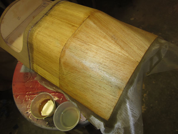
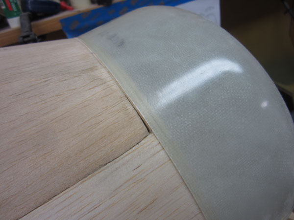
Finishing the machine gun hump fairing was done with 2 layers of .5 oz fiberglass cloth and Zap’s Finishing Resin. I did this so when I cut open the sheeting for the gun slots, the wood won’t spring out of shape. With that done, I moved onto the forward engine cowl ring. Once the resin cures overnight, I trim the cloth by rubbing the edges with 320 grit sandpaper.
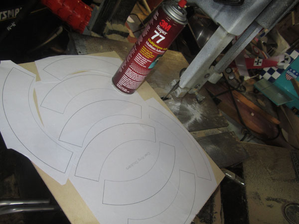
So, the next task is to add the support rings to the front of the fuselage that will support the engine cowling. To save on materials, I drew out the circles and divided them into four segments shown above. I pasted them to Lite-ply and arranged them to minimize waste.
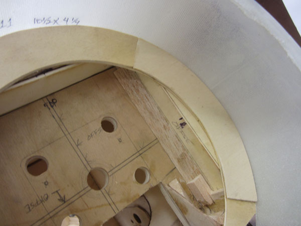
Starting with the first row (there are two thicknesses of Lite-ply rings,) I glued on the top center segment. This was placed so the outer surface of the cowling would line up with the front of the hatch cover. The two side segments were glued in place so the cowling would be centered. Once these were set, I taked the cowling in place and then added the second layer of ring segments overlapping the seams. I placed each segment snug against the inner surface of the cowling for a precise fit.
You can see through the translucent cowling here and see the two layers of ring supports. Later, I would glue the attachment blocks to the rings to accept the cowling attachment screws.
Landing Gear Continued
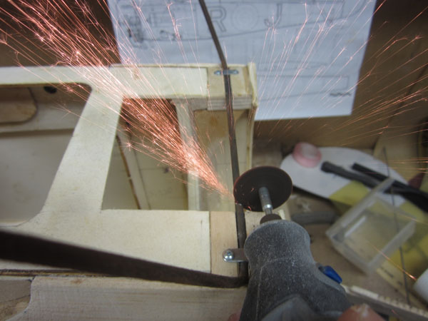
With the rings in place, I turned my attention to the landing gear. As you can see here, for the engine to fit into place I have to cut away the center cross piece of the front gear strut assembly. The fuselage is upside down here. A few moments with the Dremel Moto-Tool and a cutoff disc removed the unwanted length of music wire.
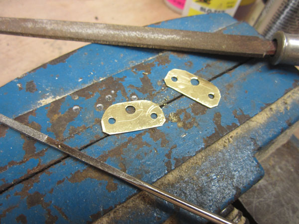
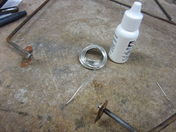
Using some brass stock, I made two anchor brackets to support the ends of the cutoff landing gear wire.
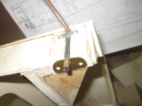
Here the bracket has been slipped over the end of the upper gear section. Notice I left about 3/16 inch of the wire past the end of the gear attachment block.
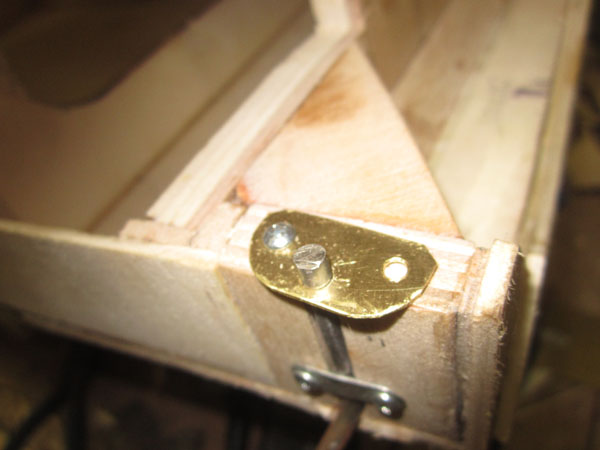
After cleaning the brass bracket, I screwed it to the end of the gear block. I then added a drop or two of liquid flux to the solder junction area.
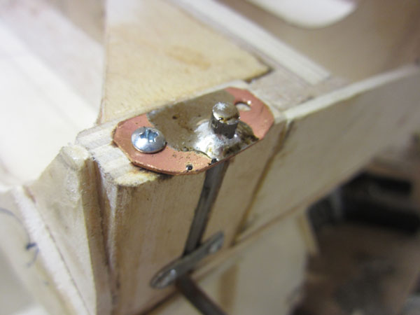
Using an 80 watt soldering iron, I applied some Stay-Brite high silver content solder and built up a nice smooth solder fillet to support the wire.
I did this to both sides of the landing gear wire. After cleaning up the flux, I also sanded the scorch marks on the gear blocks and hardened the blocks with a few drops of thin CA glue.
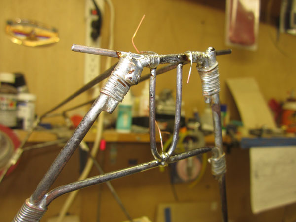
While I had the soldering iron all heated up, I continued with the lower landing gear axle guides soldering them into place.
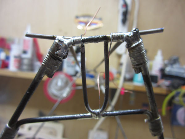
The U-shaped guides will keep the solid axle wire from shifting out of alignment while the model is taxiing. To keep the axle straight and centered, I made sure that the guide pieces were the same distance from the tail post before soldering them into place. Notice I used thin copper wrapping to strengthen all the solder joints. Later, there will be bass wood fairing stripes glued over the wire framework to finish off the gear.
That’s it for now. Next I will be working on the articulated axle wire and forming the rough wood fairing pieces for the gear’s spreader assembly. Until next time, build something scale!
To see the previous post in this series, click the link: https://www.modelairplanenews.com/blog/2014/07/22/workshop-build-along-sopwith-camel-part-10-sheeting-the-camels-hump/


Great Job Gerry! I just ordered the Balsa USA 1/4 scale Camel, looking forward to the build. You should kick this plane up a notch..1/3 scale! 🙂
Did this stall out?
Stall out? no, there are now over 30 parts to the build. Go to Modelairplanenews.com and do a search for Camel.