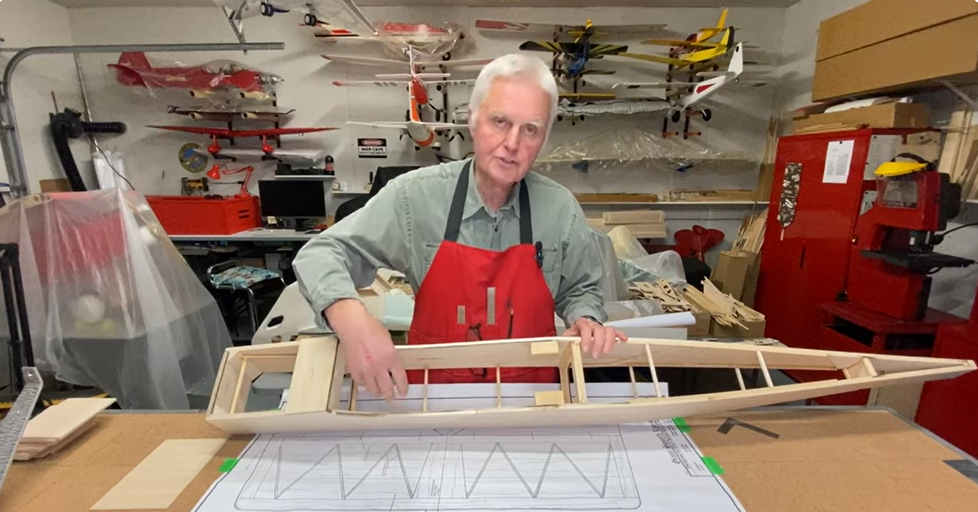
We just recently posted about our latest project, a 1960s era Fokker E.III Eindecker ideal for the upcoming Mission event at the Old Rhinebeck Aerodrome. The Mission event as well as the entire WW1 RC Jamboree is hosted by the hard working members of the Mid-Hudson RC Society club and this year is the 51st annual event.
Nick Ziroli designed the 55 inch Eindecker for this event and we thought a modern CAD drawn and upgraded version would be a blast. We continue with some photos of the wing construction.
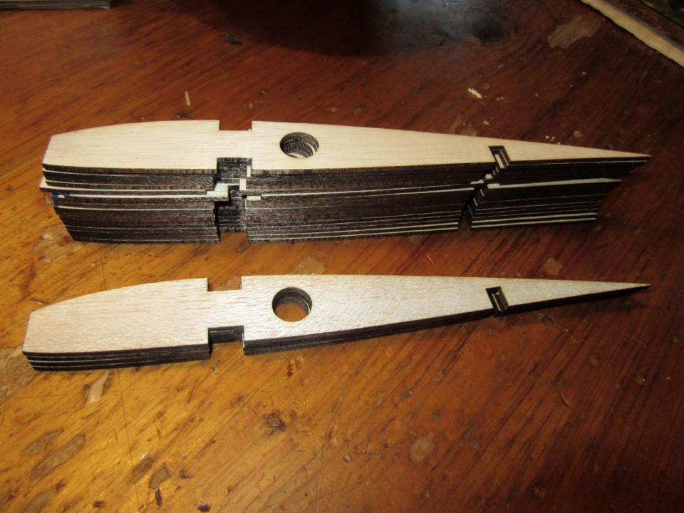
As with all the parts, the wing ribs are laser cut and use the exact same construction details Nick used back in the ’60s to produce an easy to build, sturdy wing.
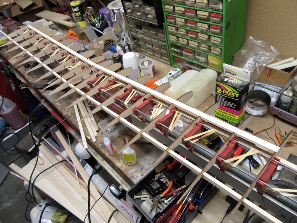
The wing can easily be build directly over the plans in the usual way, but we broke out our old tried and true A-Just-O-Jig to assemble the wing. This was the hot ticket in the late ’60s and early ’70s so we thought it was appropriate to build our version of Nick’s wing.
Holes are drilled into each wing with a template that holds all the ribs in the exact same position relative the holes that will accept the jigs alignment rods.
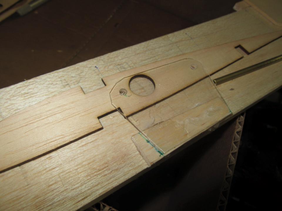
 I lost my original template/drilling fixture so I made one from wood. As can be seen, it has a clear piece of plastic to guide the 5/32 inch drill bit (or as I used, a sharpened piece of brass tubing), and a fixed leading edge centering notch. The trailing edge notch slides back and forth to accept various rib lengths.
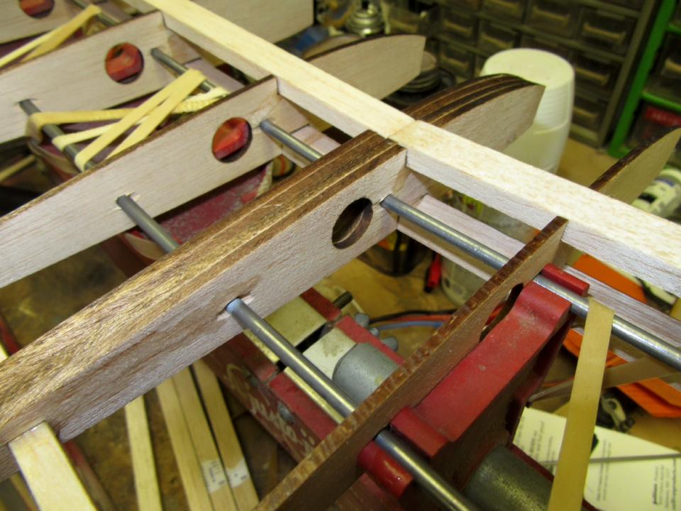
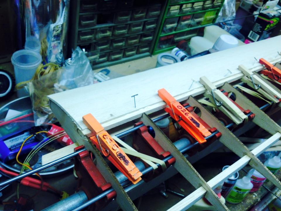
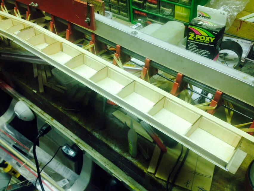
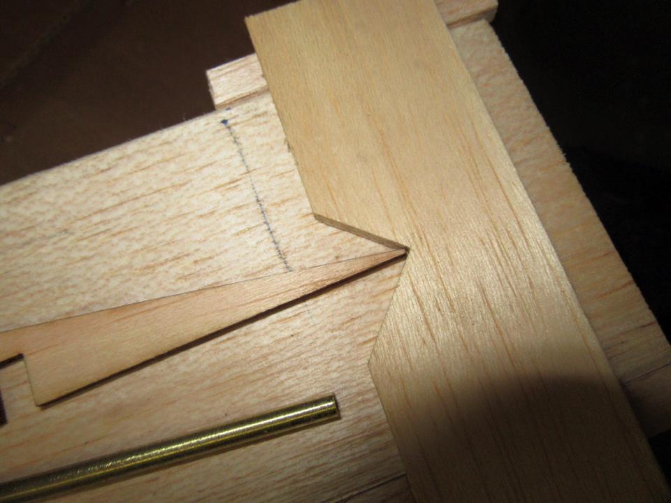 Once you place the rib in the fixture, you slide it forward as shown above, and then you bring the trailing edge centering notch forward to accept the rib’s TE. This centers the rib so you can form the holes. You do have to be sure that the holes are properly placed so the holding rods do not interfere with the lower main spar. Shown below are the center ribs with the spars in position. The holding rods are supported by the molded plastic support pieces and rubberbands are used to hold the rods down in the proper alignment.
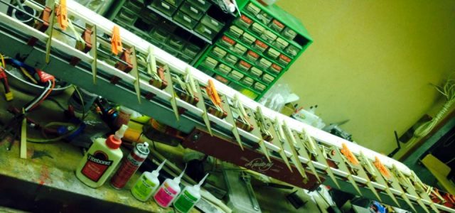
The next step is to install the aft spar and the sub-leading edge strip at the front of the ribs. Use a razor plane to trim the strip and then sand it to blend into the rib’s curvature. Now begin sheeting the front of the wing. I use both Zap glue and yellow Titebond Carpenter’s glue for all the sheeting. Yellow on top of the ribs and then Zap at the front and back edges to hold it in place along with some T-pins and clothespins.
You can position the wing any way you like so you can easily rotate it so the bottom is facing up.
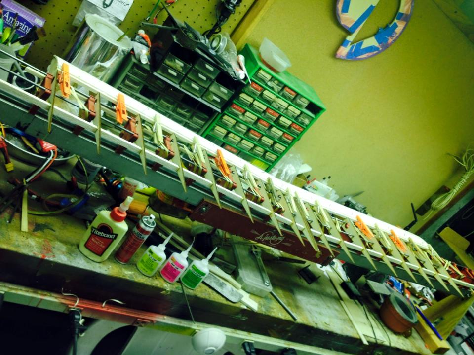
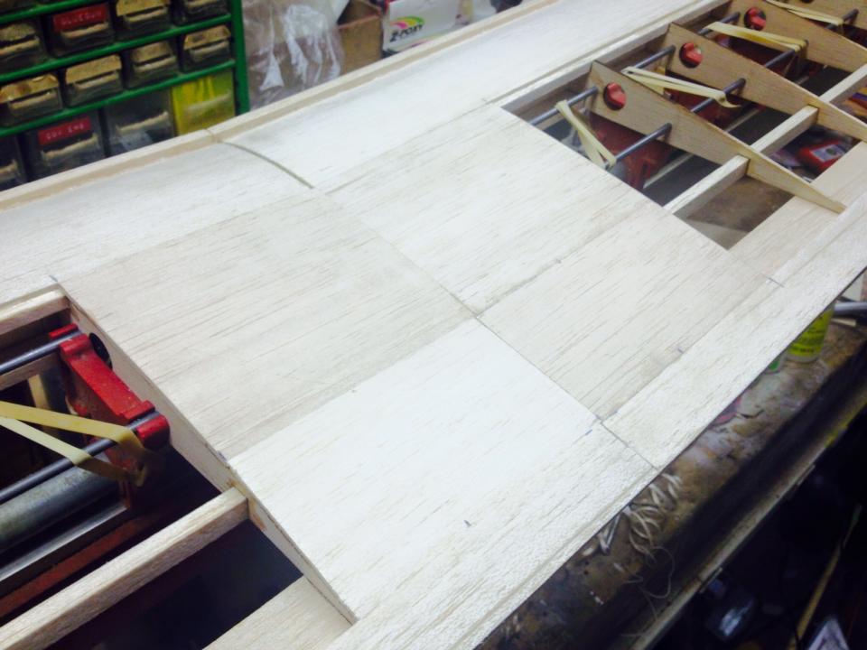
Here’s an overview of the wing with the front top sheeting clamped into place.
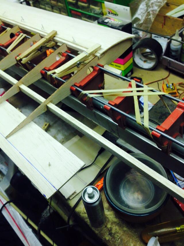
Here the lower (2 inch wide) trailing edge sheeting has been glued in place. The mark shows where the ends of the ribs should be aligned. Also not that the secondary spar is left over size (long) so it can be trimmed to length when the tips are added. After the glues has set. the top (1 inch wide) trailing edge sheeting can be added.
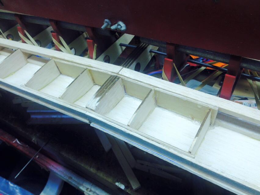
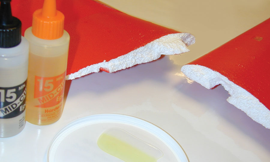
Before adding the lower front sheeting, the plywood dihedral braces need to be installed. Use a razor saw and remove material from the center section ribs, and slide the braces into place.Either Slow ZAP or 15-minute epoxy can be used, just clampo everything tight while the adhesive sets.
After the dihedral braces are in place, installed the 3/32-inch vertical grain shear webbing to the front of the main spar. This is what makes the wing really strong and ridged.
With all the internal bracking installed, you can finish the lower sheeting of the leading edge. Now flip the wing over and add the center section sheeting between the leading and trailing edges. Once all the sheeting has been trimmed and sanded straight, the leading edge can be glued in place and shaped to match the rest of the wing.
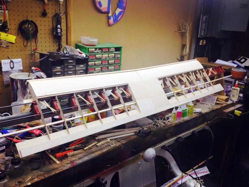
Here another overview. Notice that the trailing edges are left extra long. At this point, your can add the top and bottom rib cap strips before removing the wing from the jig.
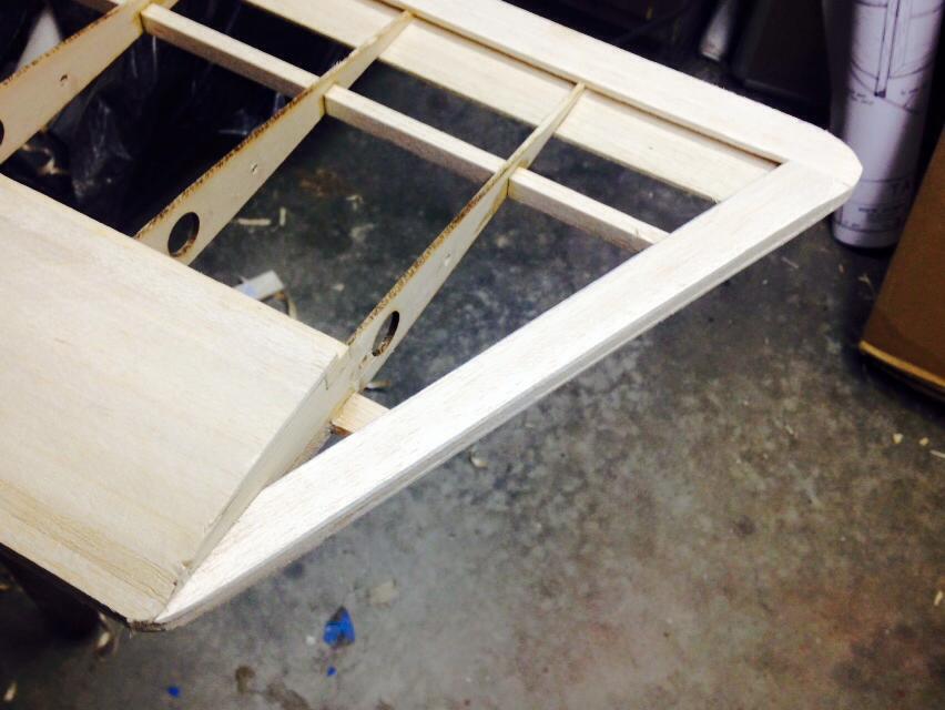
Here is the roughed in wing tip. It is pretty simple and is made from a single piece of 3/4 inch wide 1/4-inch thick balsa. It is then sheeted over with a strip of 3/32 inch sheeting to blends it into the trailing edge and the bottom leading edge sheeting.
Stay tuned! Next time, we will finish up the wing and then mate it to the fuselage so we can add the top decking and canopy section.