
Crimp-on servo connectors are tremendously useful for accomplishing neat and reliable component installations. With these connectors, you can trim overly-long servo leads to the ideal length, and you can make your own servo leads and extensions for sailplanes and giant-scale models. But there’s no denying there’s a learning curve for installing these connectors. As with most things, there are a few simple tricks that will allow you to get professional results. Here’s how it’s done.
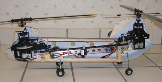
Neatly bundled servo leads make any model look more professional. By using crimp-on servo connectors, you need never worry again about where to hide all that extra wire.
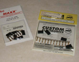 Here’s how the crimp-on connectors come packaged. Custom Electronics and MPI/Maxx are two of the most popular and most reliable brands. Be sure to buy the correct connectors for your particular brand of radio.
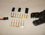
 Here are the tools of the trade: metal contacts and plastic housings for both male and female connectors and the required crimper.
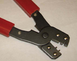 This is the crimper of choice. You can get a crimper like this at your local hobby shop for about $25, but the exact same crimper is available at RadioShack for under $10.
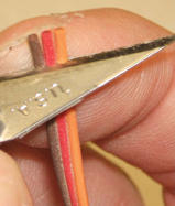 STEP 1 Now we get to work. First split the three wires apart for a distance of about 3/4 inch. I strip my wires by hand so that I have better control over how much wire I expose. I carefully score the insulation on both sides about 5/32 inch from the end and then sharply tug it off to expose bare wire.
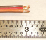 STEP 2 Here’s the perfectly stripped wire. Note that I’ve exposed about 5/32 inch of wire. The exact amount of wire you strip depends on preference, but it’s important that it matches up with how far you insert the wire into the crimper.
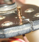
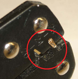 STEP 3 Here the metal contact is pre-loaded into the crimper. I’m gently squeezing the crimper just enough to hold the contact in place without actually bending the tabs. Note that the end of the crimp trough is flush with the front face of the crimper (i.e., the side that’s stamped with the wire gauges). I always use the end notch, which is for 24- to 28-gauge wire.
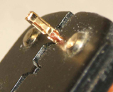 STEP 4 Here’s where it gets interesting. I’ve twisted the end of the negative lead and carefully slipped it into place. I’m squeezing the crimper grips just hard enough to hold the wire in place while I check everything over. Note that the end of the twisted bare wire is exactly even with the folded tabs of the box-loop on the contact. By using that point as a reference, I know I’ll have just enough insulation inside the crimped contact, and I know all three contacts will be the same length. Note that the correct sequence for crimping the contacts is negative, then positive, and signal last of all. When you’re sure of the alignment, firmly squeeze the crimper closed to crimp the tabs and hold it closed while you check things over.
 STEP 5 While the crimper is still closed, check the contact to see if it’s bent to one side from the pressure of crimping. If it is, gently bend it straight before opening the crimper.
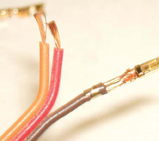 STEP 6 One down, two to go! Here’s a perfectly-crimped contact. Note again that the bare wire comes just even with the folded-over tabs on the contact. Also note that the insulation stops exactly at the gap between the two pairs of crimp tabs. This will be a strong and reliable connection.
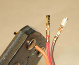 STEP 7 Here I’m crimping the last of the three contacts. This shows why I start with the negative lead and finish with the signal lead; the completed contacts are out of the way so that you don’t crush them while crimping a subsequent contact (I learned this the hard way).
 STEP 8 Nearly finished now! Here I’m gently slipping the contacts into the plastic connector housing. Note the correct sequence of leads.
-
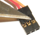 STEP 9 It’s crucial that the contacts be fully locked in place by the retainer tabs. I sometimes have to gently work the contacts in with the tip of a hobby knife so that they click into place.
 -
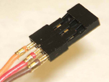
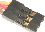 STEP 10 Here’s the finished product: a perfect connector. Note that the folded-over box tabs on all three contacts are captured by the plastic retainer tabs. Gently tug on each lead to make sure they’re properly locked in place.
 -
-BY JIM RYAN


Hi,
Is this the required crimper?
D-Sub Pin Crimper
http://www.radioshack.com/product/index.jsp?productId=2103683
You can use this one – http://www.bphobbies.com/view.asp?id=A0320106&pid=F2893843 We also carry the connectors.