By Pat Tritle
(See step by step with pictures below)
When I began flying electric-powered models in 1996, the selection of “off the shelf” propellers for electric power systems was limited to a scant few. The 8×4 and 9×5 Slimprops, and the Aeronaut 6.5×4 and 10×8 were about the only dedicated electric props available from our local hobby shop, sourced through Hobby Lobby International. At that time, we tried several different props designed for liquid-fueled engines, but found they were not particularly effective for the geared Speed 400 and belt-drive 05 power systems we were working with in the scale models we were flying.
As time went on, and electrics became more mainstreamed, the propeller manufacturers answered the call and produced increasingly larger numbers of dedicated electric props in a broad cross-section of types and sizes. Now, a newcomer to electrics has a wide variety of very efficient props for just about any kind of flying, and new sizes are coming out all the time.
There are still a few “holes,” however, in the range of propeller sizes available. For those of us flying lightweight, low-powered scale models, there’s something available that works well for most applications. However, for the model that’s running at the edge of efficiency and could use just a bit more speed or power, sometimes we just have to work with what’s available to make the system work as we’d like. Those are the applications we’ll be taking a close look at here.
Before we talk about “fine-tuning” the system, let me describe the tools that we’ll be working with. To get more speed or power, it’s not a good idea to just keep changing to larger diameter or higher pitch props without knowing the effect on your drive system. Any given drive system has a limit to the amount of current draw it can handle and still survive, so before a larger prop is installed, we must first know how near the top end of its limits the motor is already operating.
The necessary tools
To test your system, there are really only three specialty items required: the Watt Meter, a Tachometer and a hand-held calculator. The Watt Meter is designed to give the current draw, operating voltage, wattage and battery capacity consumed while the motor is running. The Tachometer gives the propeller rpm so that the “pitch speed” of the propeller can be calculated. Using these tools, we can find a prop that gives us the desired speed, without running the system beyond its limits and will determine whether or not we need to trim a larger prop to fit our needs.
Before we start, we need to determine roughly how fast the model should fly, and what propeller rpm/pitch combination we’ll need to reach that speed. There are two very simple mathematical formulas needed to calculate the stall speed of the model and prop pitch speed.
Stall Speed: Wing loading divided by 4 x 3.47. Then, multiply that number by 4 to get an approximate top speed, depending on the wing loading. Here’s a tip—the higher the wing loading, the higher the speed needs to be. This formula is only a general rule of thumb and won’t give you exact speeds. It will get you in the ballpark and serve well to get where you need to be in prop selection.
Propeller pitch speed: rpm x pitch (in inches), divided by 1056 = pitch speed in mph
Let’s use my DC-6 as an example to check the numbers. My goal here was to build a large, light model for IPS power. The 440 sq. in. model is flying at 21 oz. with a 7 oz./sq. ft. wing loading. Using the formula, 7 (oz./sq. ft.) divided by 4 = 1.75 x 3.47 = 6.07mph, we now know the approximate stall speed. Going for the top end of the speed requirement, we take 6.07 (mph) x 4 to get a top-speed estimate of about 24 mph.
Using the 4:1 IPS drives turning an 8-6 prop on a 2-cell LiPo battery, we’re turning 4100 rpm at 2.3 amps current draw, which is nearing the upper limit of survivability for the IPS system. At 4100 rpm, we get a prop pitch speed of exactly 23.29 mph. It’ll be close, but the system should work.
Using the original 8-6 prop with a 4:1 gear ratio, the model flew well, but felt like it could use just a bit more speed. The two choices to increase the flying speed would be to turn the same pitch prop faster with a higher gear ratio to get a bit more rpm, or to trade 1 inch of pitch for 1 inch of diameter using the same ratio at a cost of $1.95 per prop rather then $17.95 each for the new drives, not to mention the work involved in replacing the four drive units. Unfortunately, there are no 7×7 props ava
ilable, so if that’s the direction we take, the choice is to start with an available 9×7 prop and cut it down to a 7-inch diameter. As it turned out, the cut down 9×7 still turned 4100 rpm, and produced a pitch speed of 27.2mph, drawing 2.45 amps, which is the upper limit of the drive system. Subsequent test flights proved the new cut down props to be very successful—problem solved!
Modifying an available propeller
The only two things we need to ensure when cutting down an existing prop is that the blade length and shape is the same on both ends and that the prop is balanced once it has been cut down. One other thing to consider is that the pitch decreases as it progresses toward the tip, so when the prop is cut down, you will actually net a slightly higher pitch then if you use a prop operating at its design length. Also, this system works very well for cutting down three or four blade props as well, and really does come in handy since the selection of three and four blade props is so limited.
Actually cutting down the prop is not at all difficult. I like to build a cutting jig for each size and type prop being cut, with the major consideration being the hole size in the hub. You can also cut the prop tip completely off the prop using the razor saw, but it will damage the jig and shorten its useful lifespan. Here’s how it’s done.

A simple cutting jig was made from 1/4-inch bass wood to hold the prop so that the blade can be cut down to an accurate length. Both blades are cut against the same stop to insure their accuracy. The jig can be built to any length to accommodate any size prop. The center pin is sized to the specific type prop being cut.

Here are the tools you’ll need to custom cut your prop accurately. The jig holds the prop, and the razor saw and Handi-Cut are used to trim the blade length.

The prop is mounted in the jig with the blade against the cut-off stop and secured with a nut on the threaded shaft through the hub. After the first blade is scored, the prop will be rotated 180 degrees and the second blade scored.

The razor saw is used to score the blade, marking the exact location where the blade will be cut.

The Handi-Cut is used to clip the blade off at the location scribed on each tip.

With the tips trimmed off, the blade is reshaped with a file and cleaned up with medium grade sand paper.

The new blade shape is then traced onto a “sticky tab” to be used as a template to mark the opposing blade.

The paper pattern is cut out and placed on the other blade. The blade is then rough shaped to match the pattern.

With the rough shaping done, the pattern is removed and the blade sanded smooth.

The cut down prop is placed on the balancer and checked for proper balance. The tips are carefully sanded as needed to insure proper balance.

When the prop is balanced, it should hang level on the balancer.

A Watt Meter is used to measure the current draw of the system to insure the prop selected doesn’t overload the drive system being used. The Tachometer and calculator are used to determine the pitch speed the prop will produce.
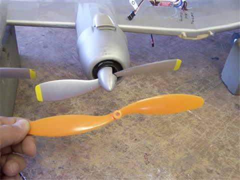
The new 7×7 prop as compared to the original 9×7. The tips can be shaped as desired when reworking the new blade.

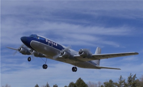
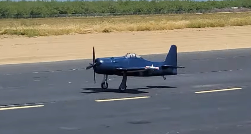
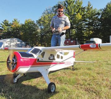
My DC-6 in flight.