Elsewhere on the Model Airplane News website, is my online review of the amazing Zing 24 Laser cutter/engraver from Epilog Laser. In learning how to use this impressive 12×24 inch laser cutter, I decided to take on of the construction plans from the Airagestore.com website and cut the various parts out to produce a kit. The airplane is a 25 size Fokker D-VII designed by Dave Johnson and for the most part I cut all the pieces as he had drawn them out. The only thing I modified was the tail feathers which I made “lock-tab” for better alignment and to eliminate the balsa strip lamination used around the edges.
This online article will be open ended and I will continue to add photos and notes as the construction process continues. This weekend (January 8, 2011) I will start by assembling the tail and begin the fuselage construction! So stay tuned, there will be lots of building tips and techniques shown. Please be sure to leave comments and questions and I will be happy to answer them for you.
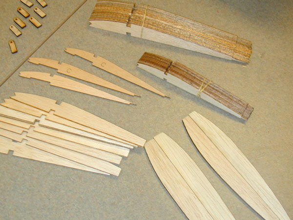
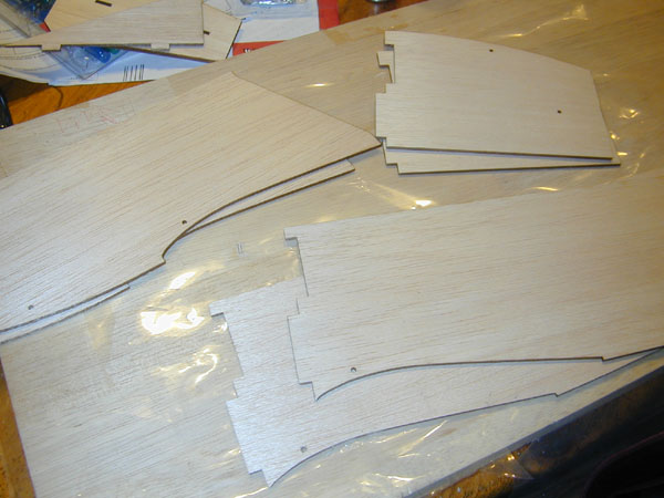
Here are some of the parts I cut with the Zing 24.
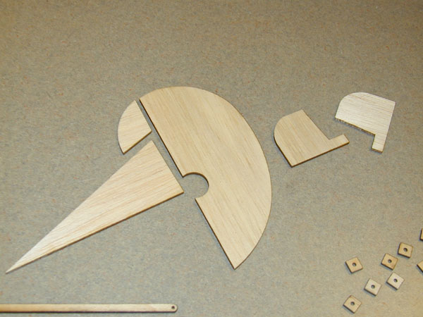
(Above) Vertical tail feathers and aileron tips cut from 1/8-inch balsa
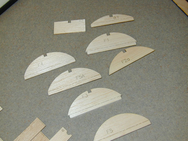
(Above) Upper fuselage deck formers
(Above) Ribs are 1/16-inch balsa while the wingtips are from 1/8-inch balsa.
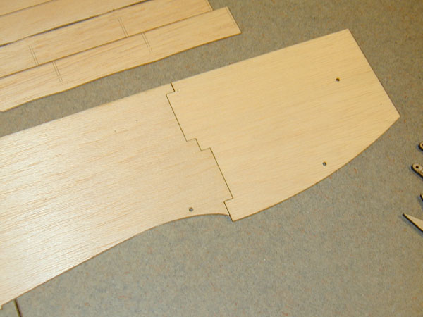
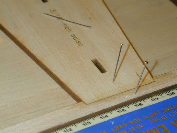
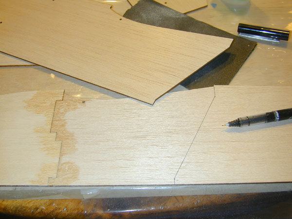
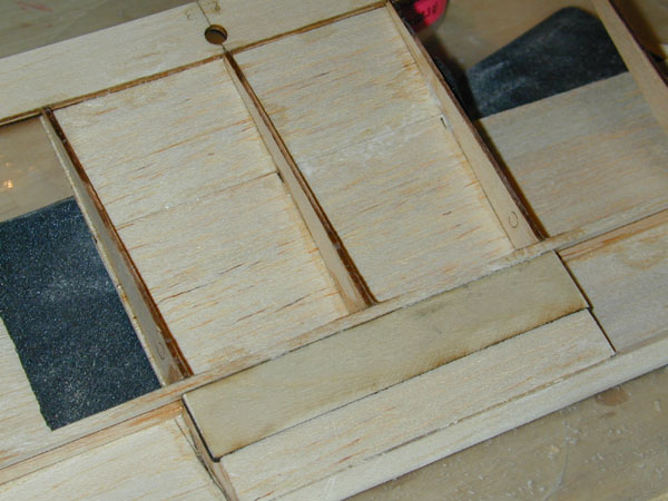
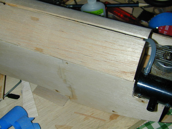
(Above) Because the fuselage is longer than 24 inches, I made this notched assembly joint. It will bee covered over by the internal forward doubler so it does not affect the strength of the balsa sides.
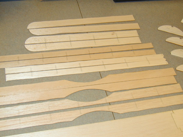
(Above) Here are the top and bottom wing’s trailing edges. The rib position lines were engraved and do not cut all the way through the wood
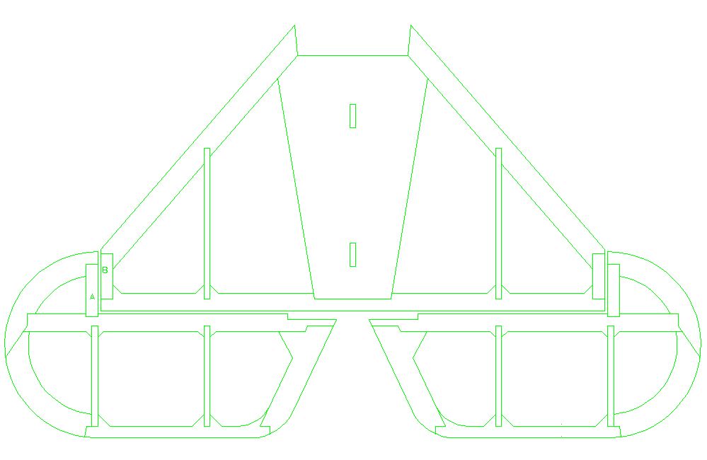
(Above) Here’s the modified horizontal stabilizer and elevator drawings used to cut the new tail parts. The assembly drawing is green because it is the assembly color I use.
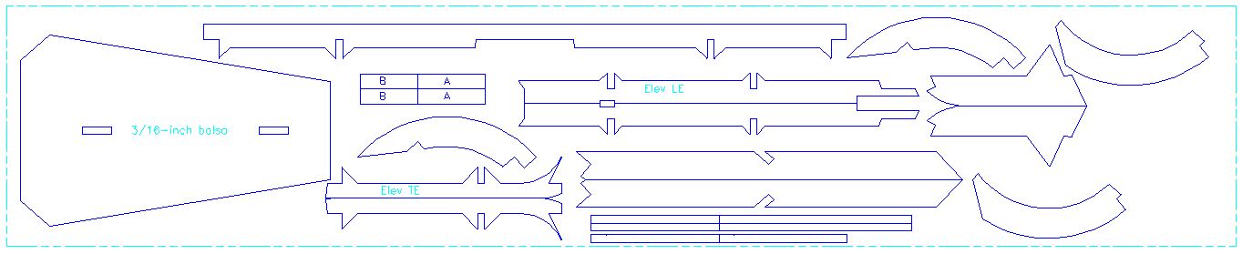
(Above) Here’s the Cut File for the tail parts. Blue is the cut color, Cyan is the engrave color and the dashed lines show the 4×24 inch balsa piece all the parts fit on.
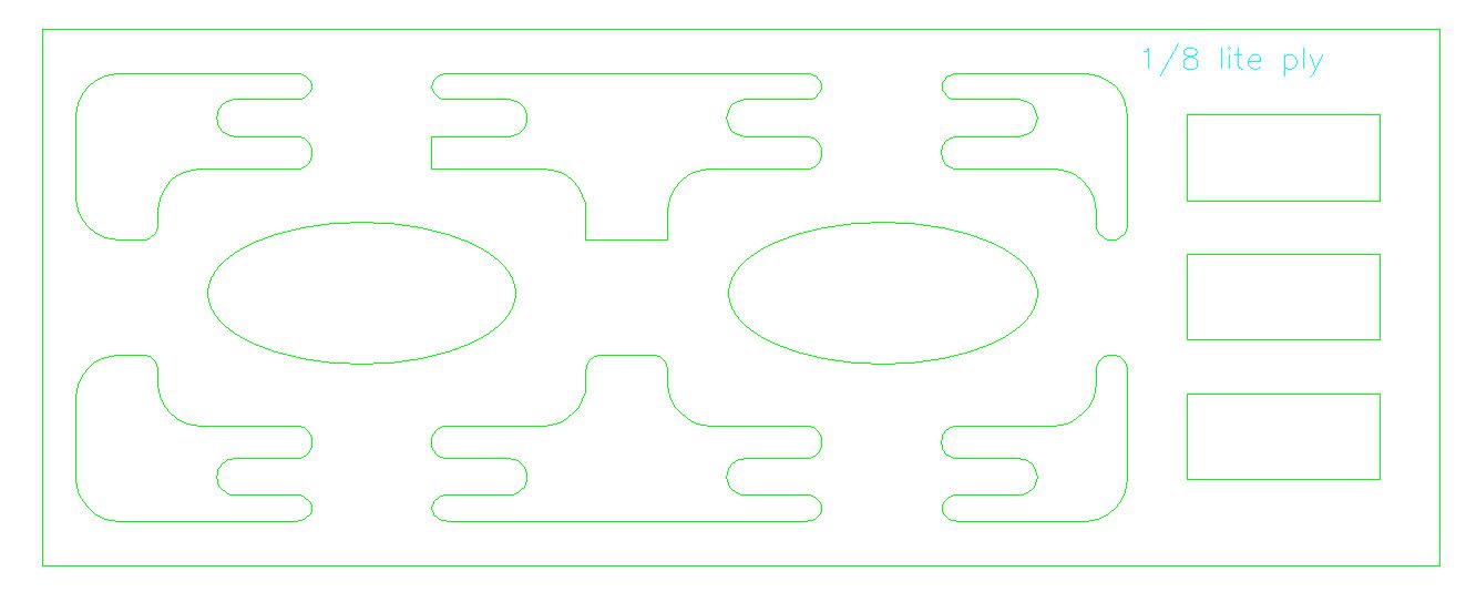
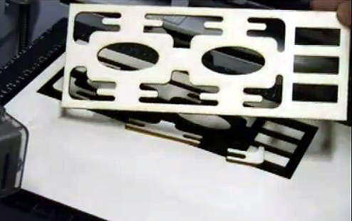
(Above) Another part I cut was a combination fuel tank, receiver and servo tray cut from lite-ply. It fits precisely in the fuselage and can be glued or screwed into place over blocks.
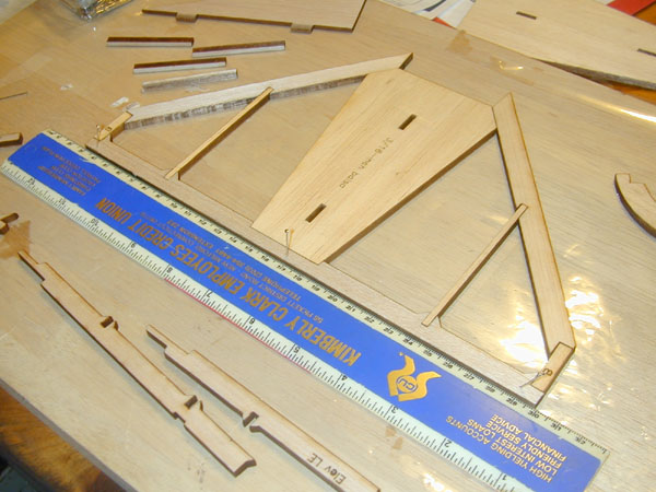
(Above) Start with a 12x24x1 inch thick balsa building board covered with Great Planes’ Plans protector clear film. I pinned down the stabilizer’s trailing edge first and used a straightedge to make sure it is indeed straight.
(Above) The fit of the laser cutting is snug. This allows the use of thin ZAP CA glue which simply wicks into the joints.
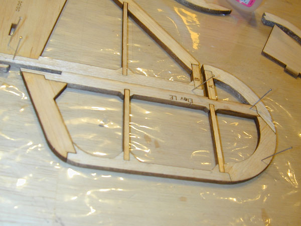
(Above) The elevator halves are built in the same way! I offset them slightly so the ZAP glue doesn’t glue them to the stabilizer.
(Above) Here’s the finished tail feathers sans the 1/8 inch x 3/16 in plywood elevator joiner. All glueing is done with ZAP Thin CA.
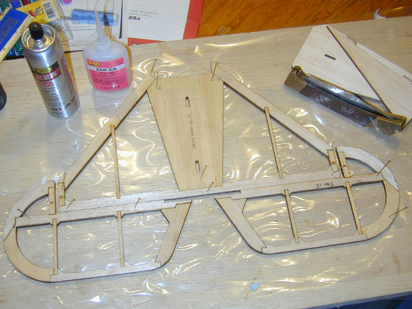
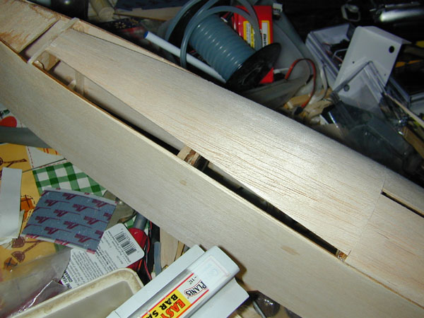
(Above) While I had the glue out, I assembled the fuselage side parts. Each side is made with three parts, the two side pieces and an inner balsa doubler.
(Above) I marked the inside surfaces of each side piece so I could glue the doublers in the correct place. It is easy to make two lefts or two right sides. The doublers cover over the joints as shown here! I spray ZAP kicker on the fuselage side and apply Medium ZAP to the inside of the doubler piece. Then slowly bring the parts together making sure everything remains straight.
Update: January 16, 2011
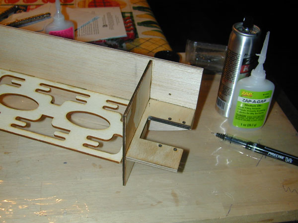
(Above) Fuselage construction starts with firewall and engine mount plate installation. Plate is glued in place even with the front of the fuselage side. I use Medium ZAP here and will use Z-Poxy to fuel-proof the engine compartment when construction is done.

(Above) The tank/receiver/servo tray goes in behind the fuselage just a bit lower than the engine mount plate so the tank will be even with the centerline of the carburetor.
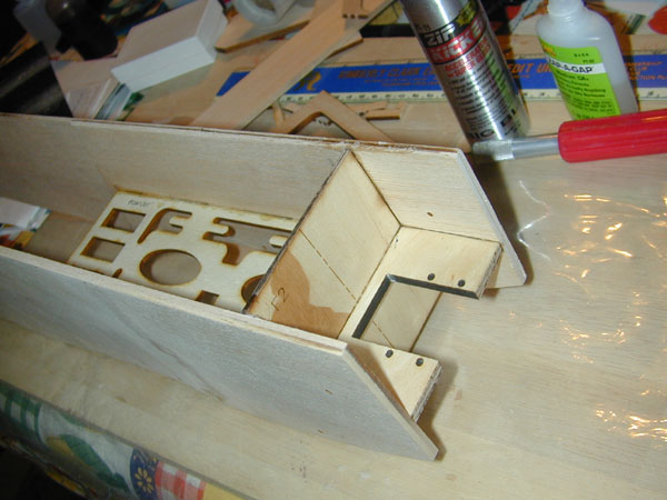
(Above) Second side glued in place. Again aligning mount plate even with fuselage side.
(Above) Upper formers and top stringer added.
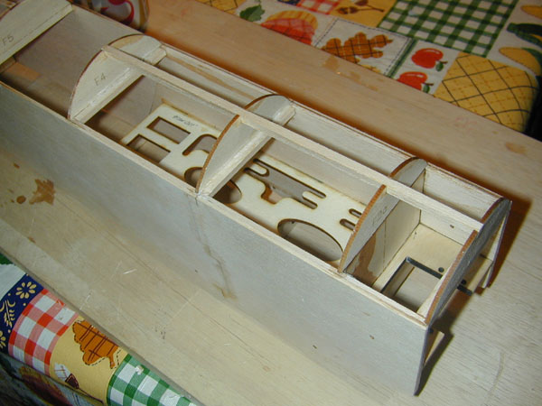
(Above) Aft formers and top stringer in place. Thin ZAP CA does the trick.

(Above) Note the stiffener cross-pieces glued to formers.
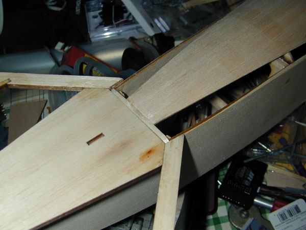
(Above) Horizontal stabilizer fits perfectly into place. Gotta’ love laser cutters.
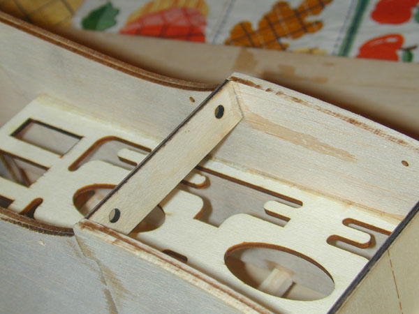
(Above) Plywood wing hold-down dowel alignment plate goes in the front of the wing saddle area.
Updated: January 19, 2011
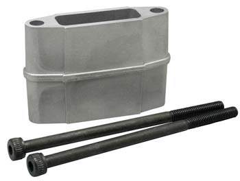
(Above) One thing that is needed for the 2-stroke engine installation is a Muffler-Extension. Here’s the one I am going to use with my O.S. .32F Available from Tower Hobbies.
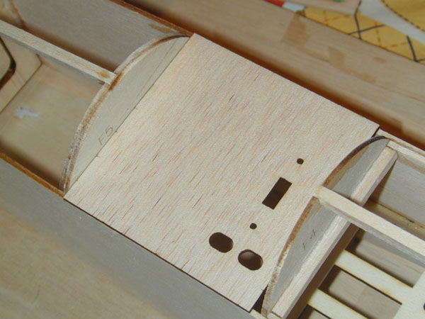
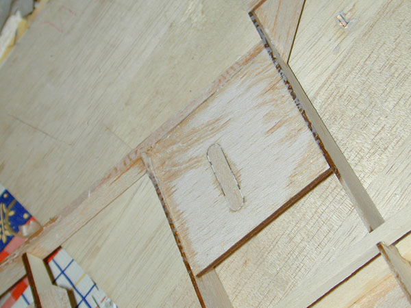
(Above) Here’s the cockpit floor sheeting. I cut in the switch opening as well as access openings for the battery charging lead. It will be glued in place cross-grain as shown here prior to sheeting the top of the fuselage.
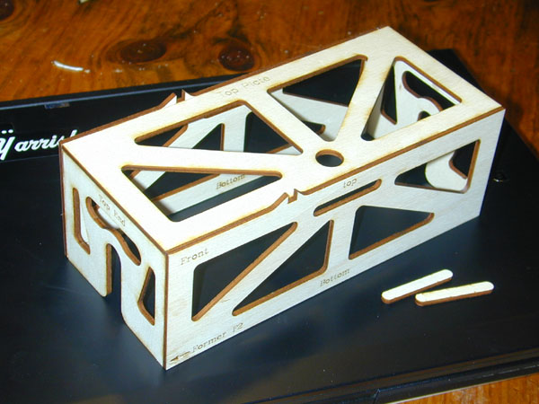
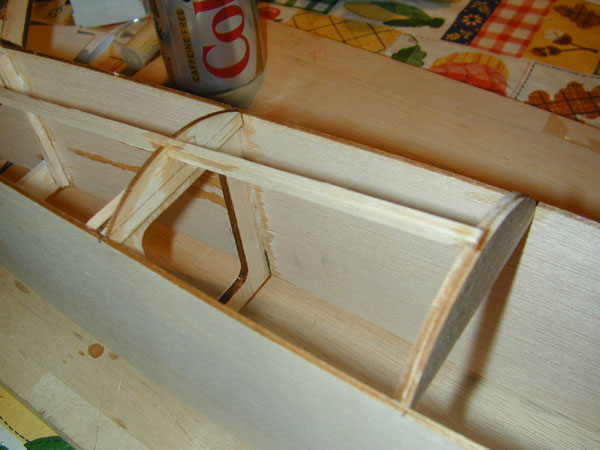
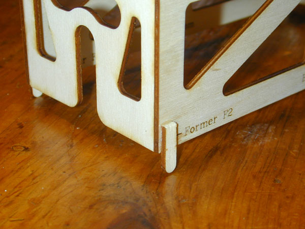
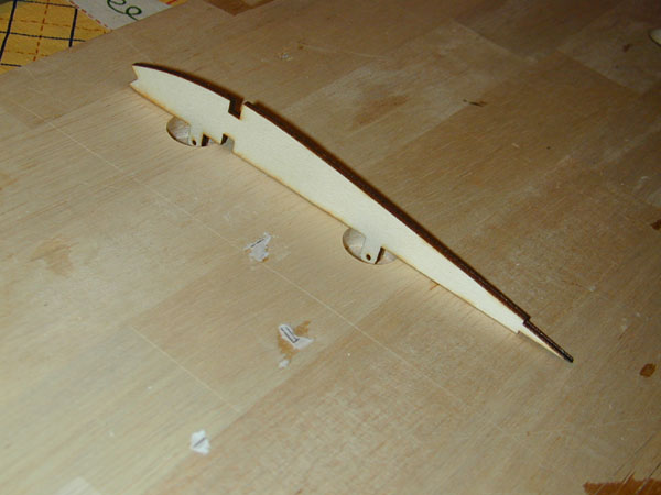
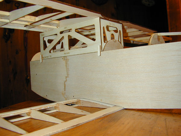
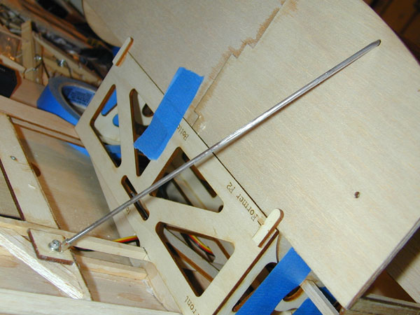
(Above) This interesting lite-ply structure is a wing alignment jig box. I use these when ever I have to postion a wing for the assembly of the cabane struts. I simply drew it on the side-view of the plans and then cut the parts out of lite-ply.
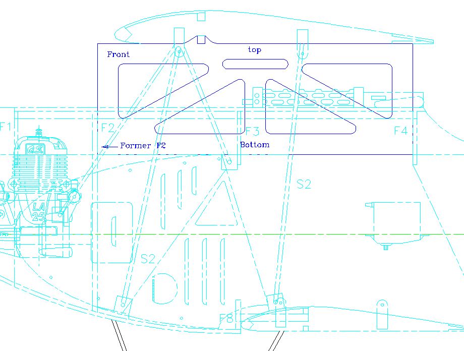
(Above) As you can see here, it fits on
top of the fuselage between fixed points to ensure proper wing postioning. For this model I made it to fit between formers F2 and F-4. F-3 fits within the box structure.
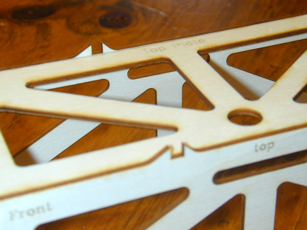
(Above) These small uprights are for the wing’s bottom spar to fit into to lock its position into place. The flat bottom wing rests in the top plate which ensure the wing is level and aligned with the fuselage.
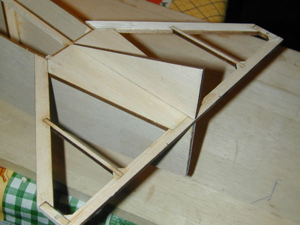
(Above) I used some of the waste pieces to make these corner alignment tabs to ensure the jig structure remains aligned with the fuselage sides and centerline. The fit is nice and tight so thin ZAP is all that’s needed.
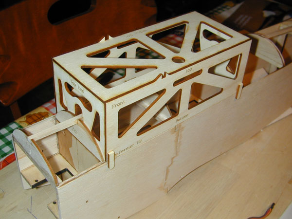
(Above) Here the alignment jig structure is positioned ontop of the fuselage. As you can see, it fits precisely and snuggly into position. You got to love CAD and Laser Cutting!
See a video of the Wing Jig being cut with the Epilog Zing 24 Laser Cutter here http://tinyurl.com/4sy5rvx
Update: January 29, 2011
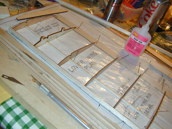
(Above) The wing is a very easy assembly, but it does require the planes for building it straight. The first half anyway. The plans are available at airagestore.com. Here the lower wing takes shape with the traling edge sheeting and lower spar pinned in place. The 1/4-inch leading edge has just been glued into place.
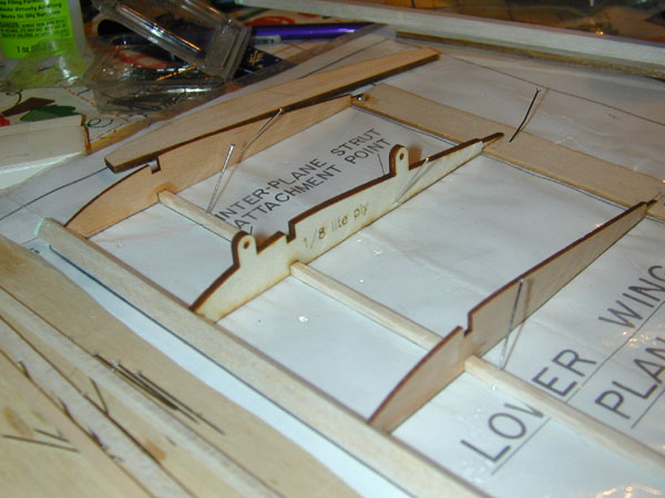
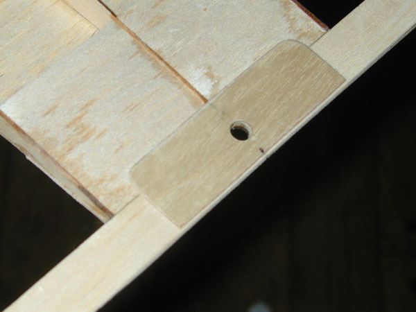
(Above) The original plans showed lite-ply attachment tabs being glued to the side of of the balsa ribs at the second to last bay. I simply cut the rib out of lite-ply and added the tabs with the holes drawn in as part of the rib. The mating ribs are in the upper wing with the tabs pointing down.
(Above) Here the 1/8 inch balsa wingtip is glued to the end rib. It sits ontop of the lower spar, and the top spar is cut and angled as shown to form the support for the wing covering. The aft surface of the leading edge is cut flat vertically so the tip can glue flush with it.
(Above) Here the upper leading edge wing sheeting has been glued into place. Not that an opening has to be cut into the sheeting for thre front strut attachment tab to stick through.
(Above) To provide covering purchase around the aft strut attachment tab, I simply glued some scrap balsa to either side of the rib as shown here. The balsa is glued flush with the top of the rib.
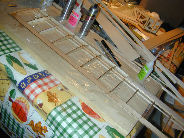
(Above) The second half of the wing is built by removing the first half from the work surface and flipping the wing around. Use a straight edge to make sure the second half is built straight and aligned with the first half.
(Above) After the two halves of the wing are completed, the center top of the wing is sheeting with then the structure is removed from the building board. Everything is sanded to shape and the leading edge is sanded smooth to blend into the rest of the ribs.The notches in the bottom of the three center ribs are for this plywood hardpoint for the landing gear to bolt to. There is a scrap piece of balsa sheeting glued in front of the plywood and then sanded and smoothed into place so the covering would cover everything without any sharp edges showing! There is no lower wing sheeting in this wing design.
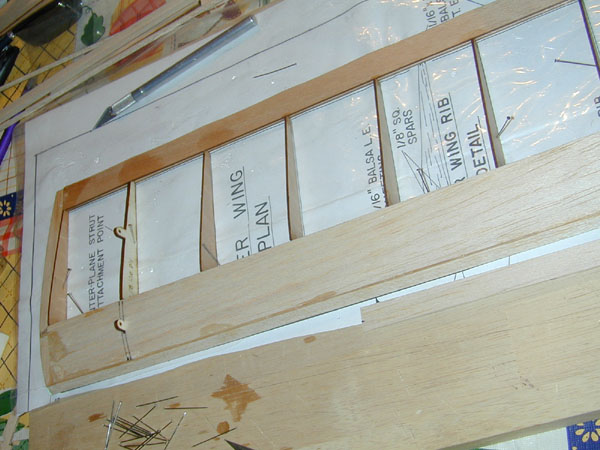
(Above) To build the top wing (with its strut attachment tabs pointing down,) I drilled a couple of holes in the building board. These allow the ribs to set flat on the building surface.
(Above) The top wing is built just like the bottom wing with the exception of the ailerons which are build along with the wing structure. I used 3/16-inch square spruce for the wing spars.
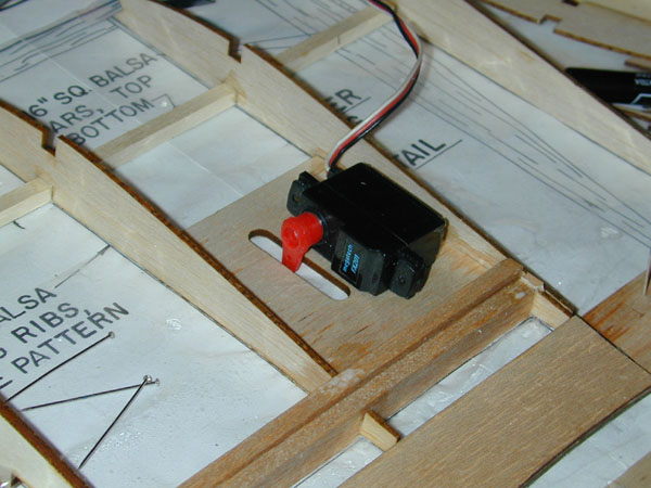
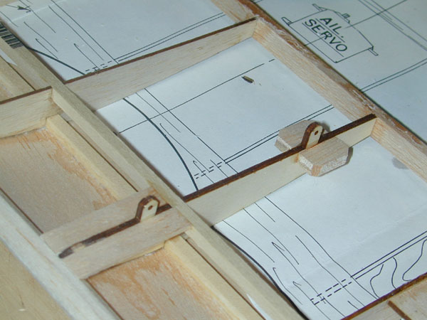
(Above) The orginal plans had a single servo in the center section of the wing, but I added these slotted servo supports and will have one servo in front of each aileron.
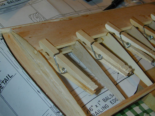
(Above) Clothpins clamp the leading edge sheeting in place onto the spar while the glue dries. The front of the sheeting is then bent into place and glued to the LE strip.
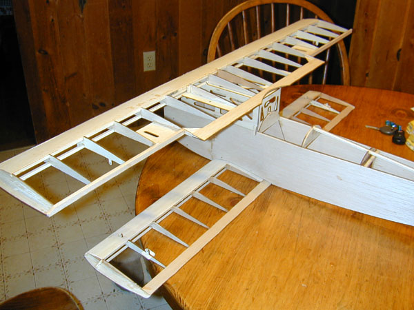
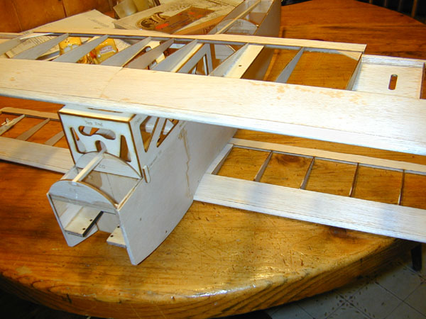
(Above) Here the wing panels are being fitted to the fuselage. They fit perfectly the first time with no asjustment. The support Jig box is holding the top wing in place above the fuselage.
(Above) The laterial placement of the top wing is fixed by the position of Fomer F2 which the alignment box fits up against.
(Above) Another view of the wings being held in place with the jib box. The next step is to install the 4-40 blind nuts in the holes in the top wing and bend the cabane struts to fit and solder them together. Once the struts are made, I will finish sheeting the top of the fuselage.
(Update February 21, 2011)
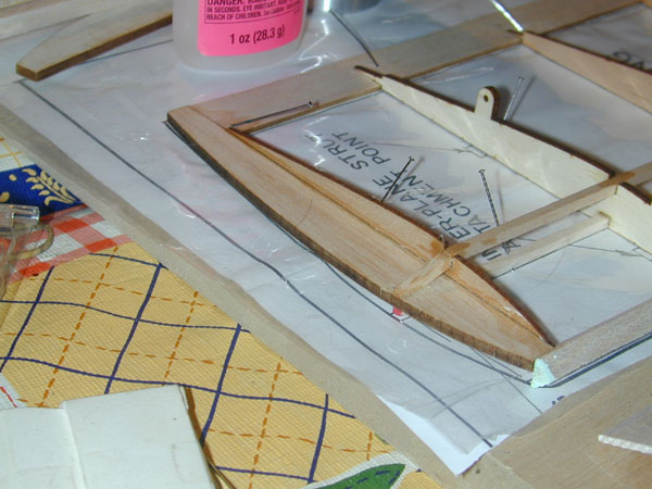
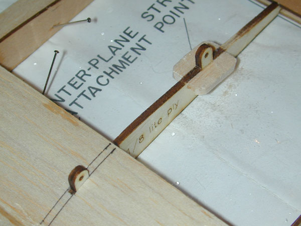
(Above) The top wing also requires covering purchase around the interplane strut attachment tabs.

(Above) The two lite ply plates installed in the top wing are for attachment of the cabane struts. 4-40 blindnuts fit into the laser cut holes.
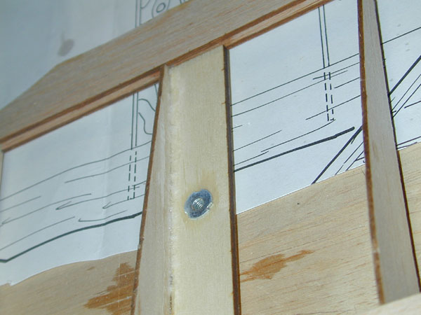
(Above) Thin Zap holes the blindnuts securely and prevents them from popping out of the holes after the wing is covered.

(Above) Use tape to secure the top wing to the alignment jib box. Make sure the wing is centered by measuring the distance between blindnuts and the sides of the jig box. They should be equal distances. For this one it is exactly 2 1/2 inches to the centerline of the blindnuts.
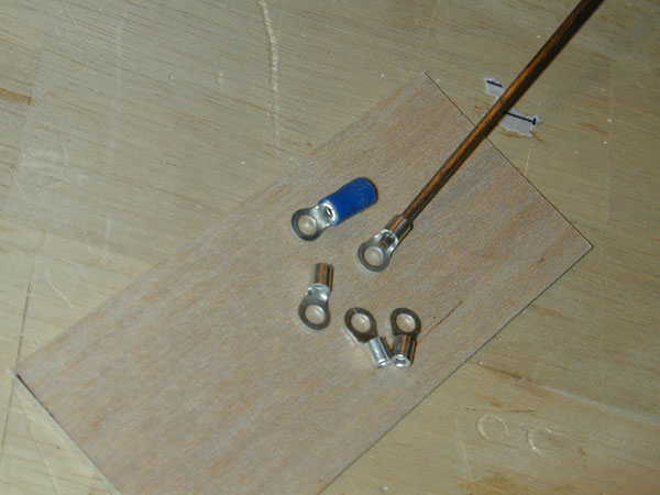
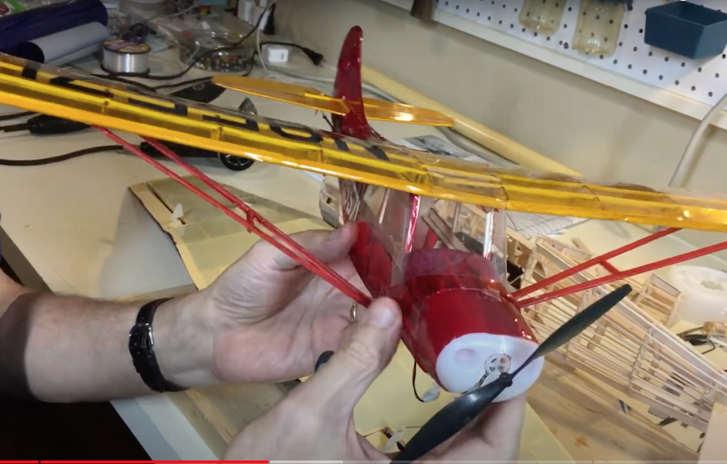
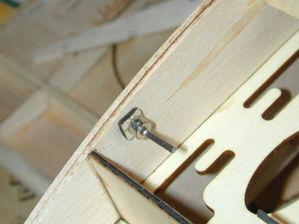
(Above) The attachment points for the cabane struts are made from wire terminals. Find a set that fits the diameter of the wire used for the struts. Here I am using 3/32 inch diameter terminals. The wire I use is 3/32 inch welding rod material. It is mild steel, is easy to bend and comes coated with an easy to solder copper coating.
(Above) Place the wing and fuselage upside-down on the bench and then loosely attach the terminal to the attachment plate with a 4-40 caphead screw. Bend the first cabane strut to shape and set in place. It is helpful to remove a little material from the terminal’s barrel so the head of the screw fits easily when tightened into place.
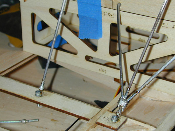
(Above) Secure the bottom end of the struts with a plywood hard-point and a lock collar. Do the same for each of the other struts.
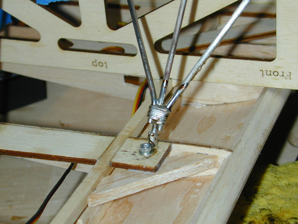
(Above) Each of the front three struts should be bent to meet just under the attachment terminal and they are wrapped with thin copper wire. I use
d Stay-Brite liquid solder flux and high silver content solder to make the solder joints. I used a wide tip 50watt soldering pen to make the joint.
(Above) I soldered both of the front triads and then checked the wing’s alignment with the tail of the fuselage and then soldered the rear cabanes into place. Use the solder and flux sparingly.

(Above) Unscrew all the attachment screws and then remove the wing alignment jig box. Once the wing is removed, use some acetone or alcohol to clean all the solder joints. Leaving the flux on the struts will cause the solder joints to corrode.
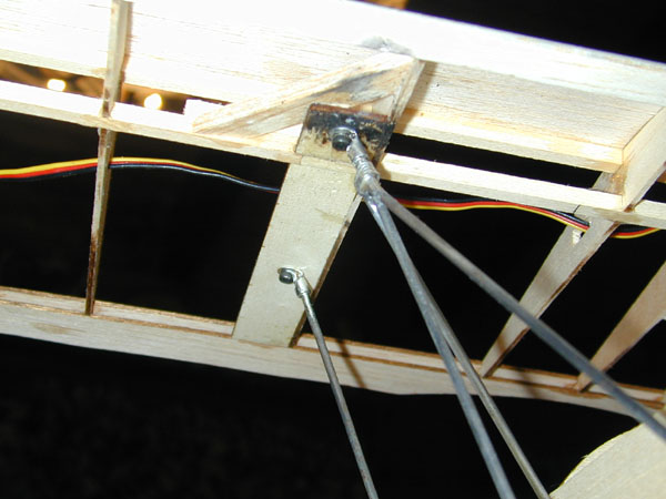
(Above) Be sure to apply the heat quickly and make the solder joint flow into the joint and remove the heat. As you can see, I allowed the heat to build up a little too long on this strut triad. If this happens to you, sand off as much of the scorched wood and then seal with a little clear dope or polyurathane.
(Above) Laser cut parts are only as accurate as the CAD drawings. I drew the servo platform incorrectly placing the servos so the case protruded above the top of the ribs. The fix is easy enough with some scrape balsa and some hobby filler.
Update: March 10, 2011
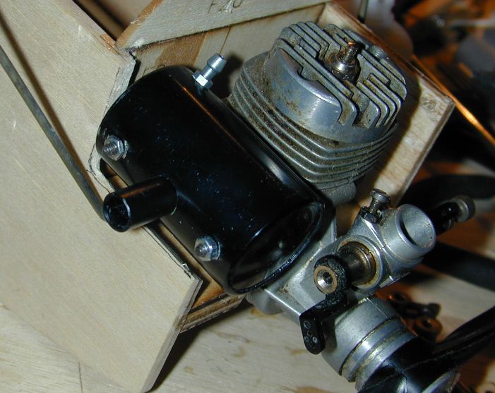
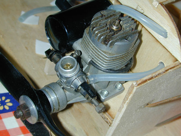
(Above) For a muffler I tried to use a simple extension and bolt the standard muffler to the engine but this interfered with the front right cabane strut triade. So I used this nice little compact Irvine 25 Mk.II silencer intended for the O.S. 25. It fits the O.S. 32FX perfectly and has the same diamter exhaust outlet.
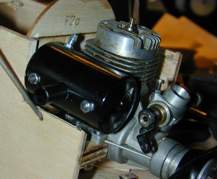
(Above) as you can see, the purchase for the front cabane strut is pretty thin. I added a 1/8 inch plywood spacer plate to the motor mount to raise the engine. I will also add an internal aluminum angle bracket to support the inside of the cabane. The inside of the fuselage and ontop of the engine plate will be finshed with a layer of fiberglass cloth and epoxy resin.
(Above) With the engine in place, I worked out the fuel tank installation. Keeping it simple, I used a 2-line setup with the vent attached to the muffler. A 1/4-inch hole in the firewall and in the balsa top former are all that’s needed to run the fuel line.
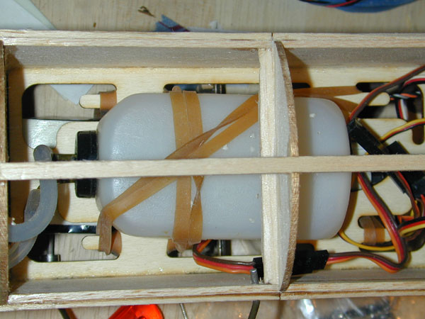
(Above) Here you see the Du-Bro 4 oz. tank in place. The lite-ply tray cutouts serve as anchors for rubberbands to secure the tank. The tank is also held with double sided foam tape.
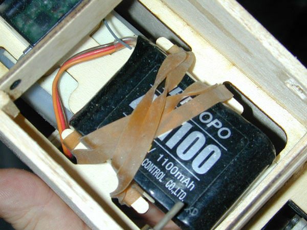
(Above) Below the tank tray is where the Rx battery goes. Again rubberbands and foam tape hold it securely in position. A 1000mAh 4.8V provides plenty of power for the smallish glow powered airplane.

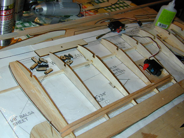
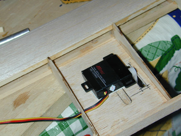
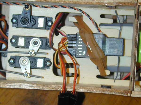
(Above) You can see that the lite ply tray running the full length of the radio and fuel tank compartment makes installing the radio gear quick and easy. The servos here are ready for the servo arms to be installed so I can run the elevator and rudder pushrod linkage. All this done before adding the lower fuselage sheeting. The Spektrum AR9000 9-channel receiver is over-kill but all I have as a spare for now. Later it will be replace with a smaller less expensive 5 or 6 channel unit.
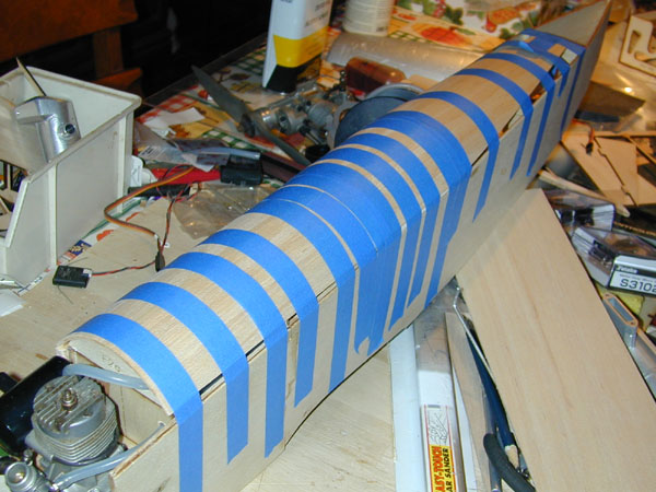
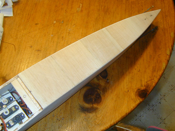
(Above) The upper fuselage sheeting is being formed to shape here. I wet the outer surface of a 4-inch wide sheet of 3/32-inch balsa and tape it in sections over the fuselage formers. There are three sections: the forward fuselage to instrument panel, the cockpit section, and the tail section. Once the wood has dried overnight, I will remove it, split it down the center and glue it in place overlapping the top edges of the sides.
Update: March 20, 2011
(Above) Here the tape has been removed and the edges sanded flush with fuselage side. A second balsa strip will be added to finish off the sheeting.
(Above) The plans show the sheeting complete from side to side, but I added a turtledeck back that’s more scale looking. And it helps minimize tail weight.

(Above) The stabilizer plateform helps keep the tail taper constant and gives move material to glue the stab too.
(Above) The turtledack sheeting ends at the last former and brings the covering surface flush with the top of the stabilizer when it is installed.
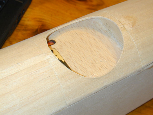
(Above) Using one of my Williams Bros’. Wheels as a template I cut out a curcular cockpit opening. Here you can also see the final balsa strip at the center top of the front decking. This is also sanded to flush out the joints.
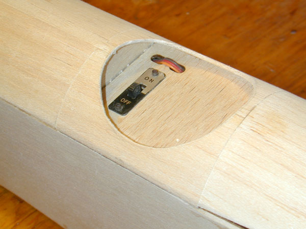
(Above) Here you see the simple switch and charging lead arrangement. The lead is pulled out for charging and then the end is fed back into the second opening! This basically finishes the fuselage construction except for the bottom cross grain sheeting which I will add after I install the rudder and elevator pushrods! Also the landing gear hard points will be added after the bottom wing is installed.
March 30, 2011 Update
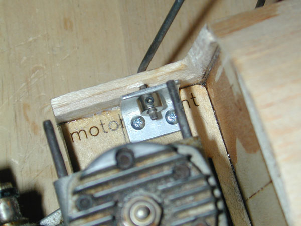
(Above) Because so much material had to be removed from the fuselage side, I added this simple aluminum bracket to reinforce the cabane strut hard point.
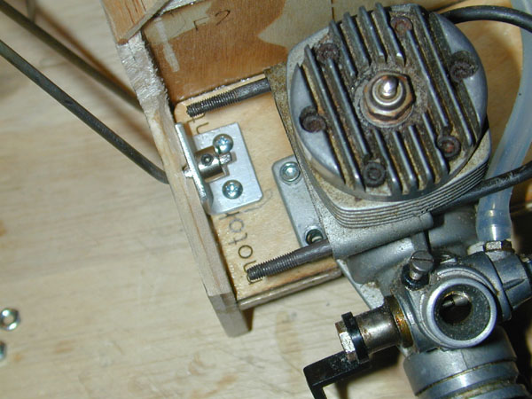
(Above) As you can see, there are two pan-head sheet-metal screws securing the bracket to the engine mount plate and a hole drilled in the vertical portion, accepts the bottom of the cabane strut.
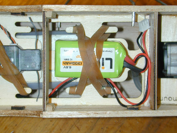
(Above) The LiFe battery replaces the 4.8V receiver pack I had originally installed. The 6.6V works great without a voltage regulator.
(Above) Also, the larger 9-channel receiver was replaced with the Spektrum AR
6000.
(Above) The fuselage bottom is sheeted with the standard cross-grain balsa with 1/16-inch thickness.

(Above) Before the cross-grain sheeting goes on, the rudder and elevator pushrods go in. I used 2-56 pushrods with Sullivan clevises. The center of the push rod run is also supported with vertical balsa sheeting. I also added the platform under the horizontal stabilizer to increase the gluing area.
(Above) the center of the wing under the attachment screw is supported with 1/32 inch plywood.
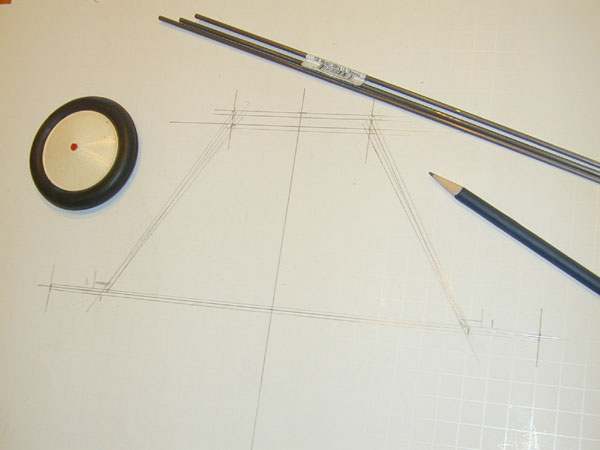
(Above) Next step is the landing gear. I like to use a large graph paper poster board and draw out the front views to workout the geometry. The lengths of the strut wires is taken from the side view of the plans.
I’am going to the Toledo show tomorrow so I will get back to the landing gear when I get back.