
After finishing up my landing gear and the hinging of the tail surfaces, the next part of this build-along project is the radio gear and the control linkages.
Starting at the front, I installed the engine and then the servos so I could work out the throttle linkage.
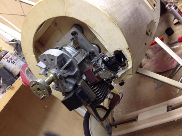
Here the engine is bolted onto the firewall with the soft-mount bolts and rubber isolators. This spaces the carburetor properly in relation to the servo arms.
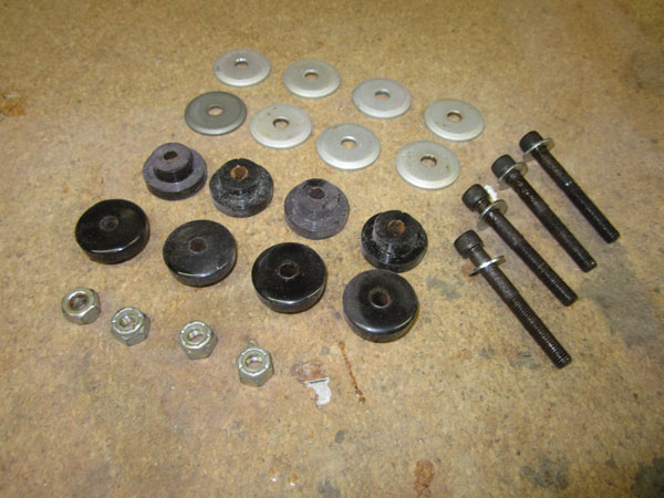
Here’s the bolts and rubber isolators used to attach my Zenoah G-38 to the firewall.

Another thing that was fixed was to add some clearance space between the intake venture fitting.

To hold the servos, and the battery pack and the receiver, I installed this equipment tray. It is screwed into place and is removable. You can see the throttle linkage passing through the firewall through the opening for the inset muffler. I am using the HV digital 821 JR servos. Awesome smooth action.
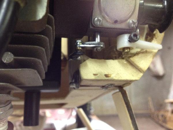
Here’s the throttle arm connected to the throttle linkage. The large white tiller arm is for the choke.
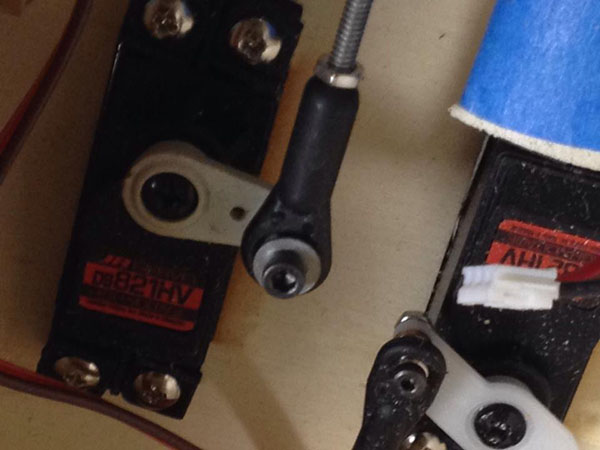
At the servo end of the linkage and pushrods, I used ball link clevises. I think these are the most secure and most slop free way to transfer servo motion to the control linkages.
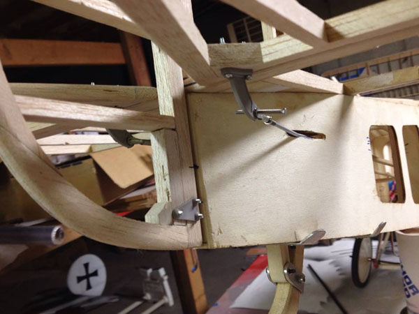
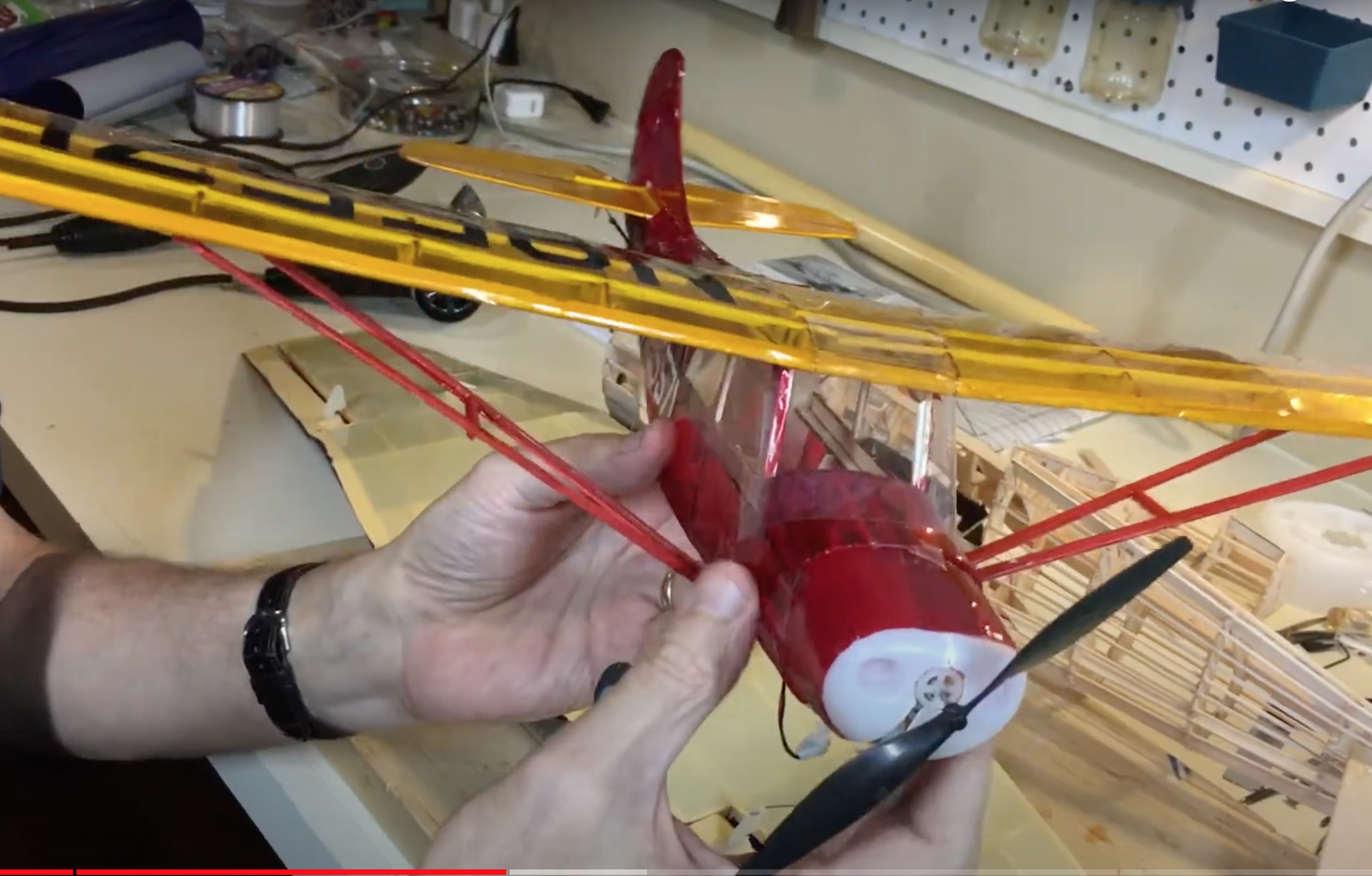
Here is the temporary elevator control linkage installation. I am using threaded 4-4o wire rod ends and Robart ball link control horns and clevises for the control linkages.
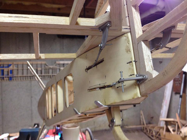
Here on the left side you see the rudder and elevator 2 control linkages.
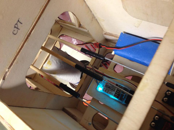
For the pushrods I used old school 1/4 inch birch dowels. The rod ends are 4-40 threaded wires from Sullivan Products. I bent the end 90 degrees to match a hole cross drilled through the dowel. I then wrapped the wire with thread and CA glue and then covered the joint with heat shrink tubing. I cut a groove in the end of the dowels for the rod end wire to fit into. Very strong and very easy to do. You can see the JR Americas’ receiver glowing bright blue in the photo. Love it!
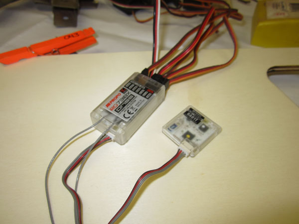
Here’s the receiver I am using. it is the RG738X from JR Americas.
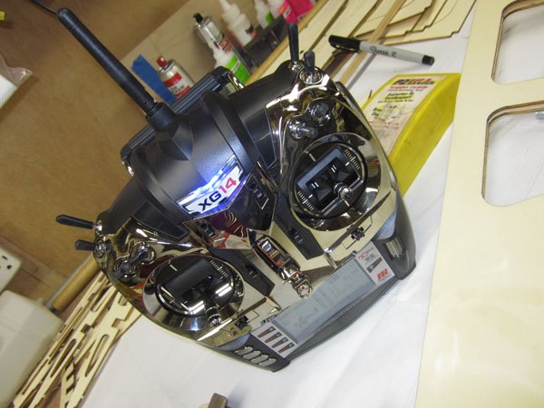
Transmitter for the Camel is the XG14 from JR Americas. All that’s left is to setup the fuel plumbing and work out the fuel tank installation and the Camel is just about ready for covering! Stay tuned.


Gary it has been a long time since we talk. I been working on this camel for years now and I am finally at the end and almost finished. I do have a quick question, do you use two servos for the elevator due to the split fuse elevator? I notice you have three dowels going to the rear of the plane. I was planning on using one servo and use a link to move both with one rod. please advise.