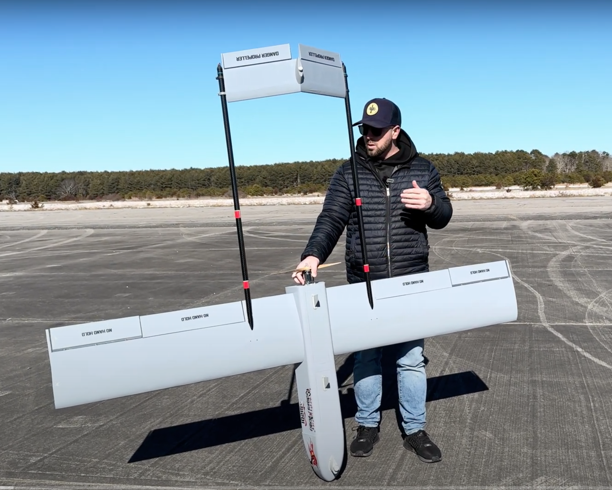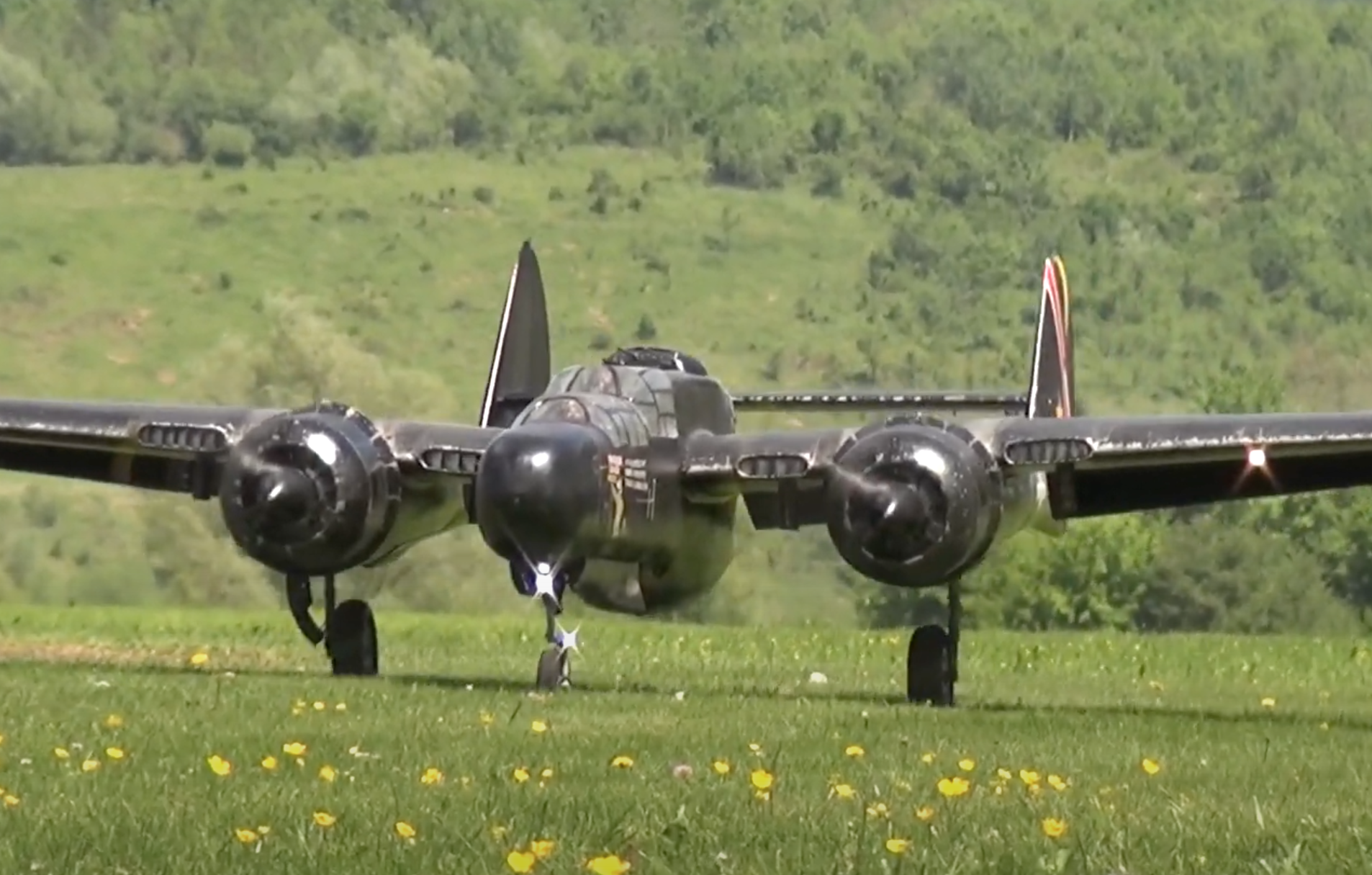
Tail rotor design in full scale helicopters is an on-going science to reduce weight, noise, and power requirements while increasing efficiency and stability. Although these same design parameters are also important to our model helicopters, their effects are a lot less noticeable and can be overcome without seriously degrading flight performance. As an example, if the control system of our tail rotor is not as efficient as it could be, we simply install a more powerful servo to handle the extra loads. This would require a larger battery to power the servo and then possibly a larger engine to lift the extra weight of the larger battery. Since we have no way to measure the efficiency of our helicopters, or their components, and we have more than sufficient power in both our engines and batteries, efficiency is not much of an issue.
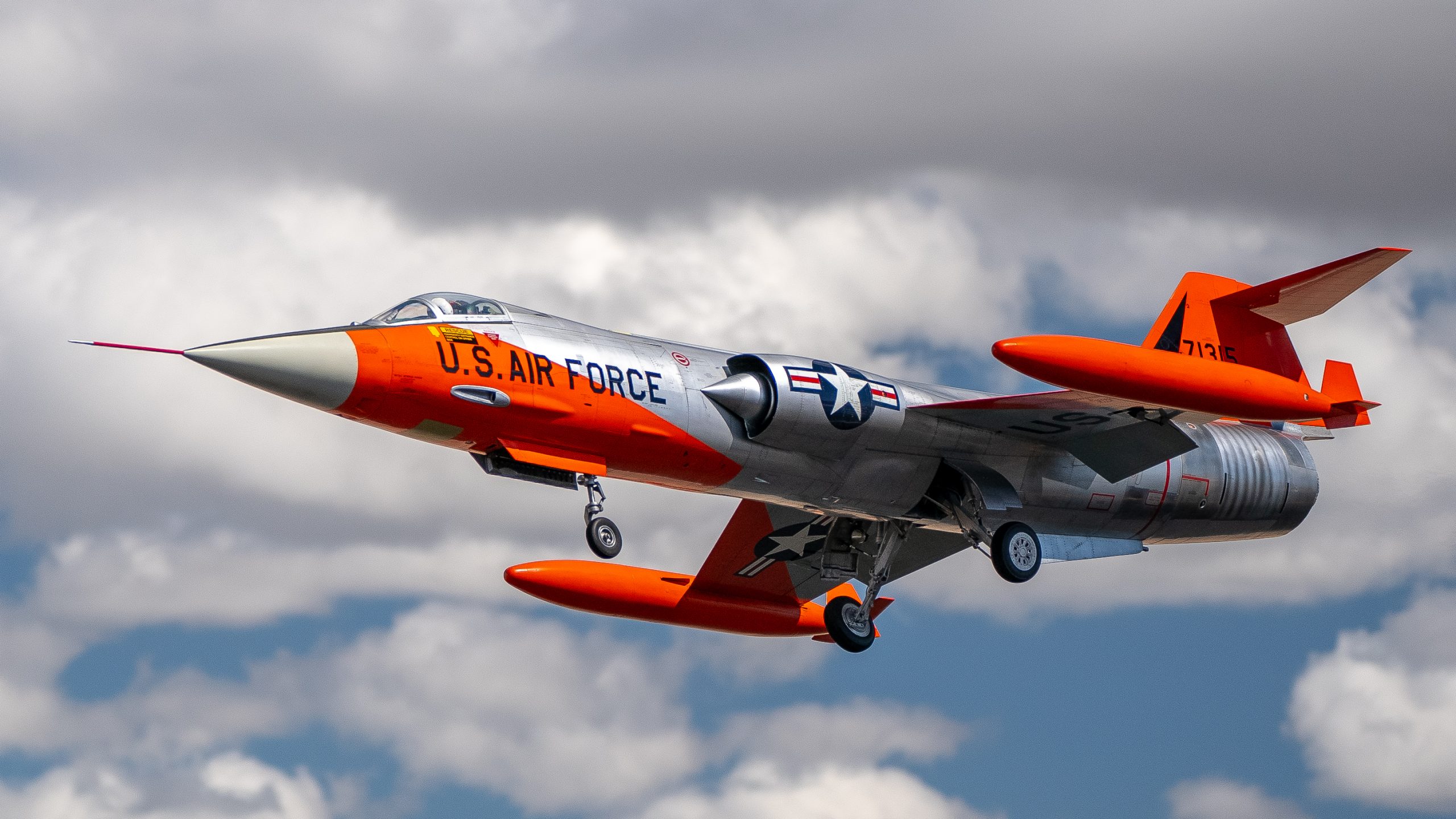
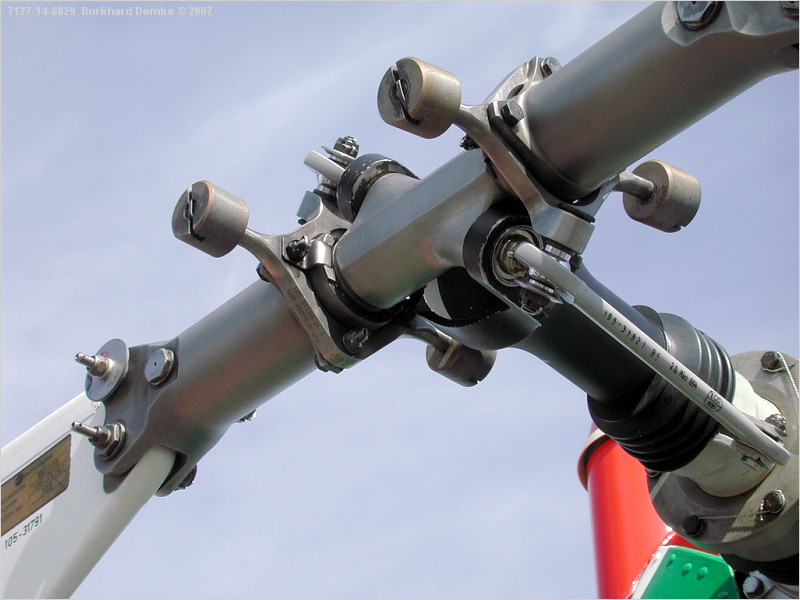
Full-Scale Tail Rotor Design – Note in the photo of the full scale tail rotor that there is a center pin in the tail rotor hub that allows off axis tilting of the rotor plane. Years ago some of our model helicopters had this soft mount tail rotor design feature, and I believe it was called a Delta Stabilized Tail Rotor. However, such a design would require a soft mounted “flapping” tail rotor system, which is exactly the design of this full scale helicopter tail rotor. Such a design reduces vibration and stabilizes the tail rotor, but this is no longer used in our models since we only have hard mounted tail rotors that do not allow a flapping motion.
The most notable design features of the full scale tail rotor are the four weights that are used to reduce control power to the tail rotor. As the tail rotor turns, the rotor blades must be held in position to produce thrust to control the nose position of the helicopter. It is this tail rotor thrust that is used to counter the torque of the main rotor system, which is why the tail rotor is called an “anti-torque device”. As we know, the pitch of tail rotor blades can be changed to vary their thrust, which in turn produces larger aerodynamic forces on the tail rotor blades, which must be overcome by the tail rotor servo. However, these same aerodynamic forces try to streamline the rotor blades, providing positive pitch stability to the tail rotor. We have all proven this to ourselves when we held our hand out a car window as it’s going down the road. Relatively little effort is required to keep our hand flat to the wind, but if we angle it up or down, even slightly, a great deal of force is required to keep it in that position. Relaxing our hand will bring it back to the streamlined, low drag, position. And the same is true for our tail rotor blades. Now, wouldn’t it be nice if we could design a counter-force devise into the tail rotor to reduce, or even eliminate, these aerodynamic forces that our tail rotor servo must contend with? Well, this is exactly what those four weights are designed to do.