

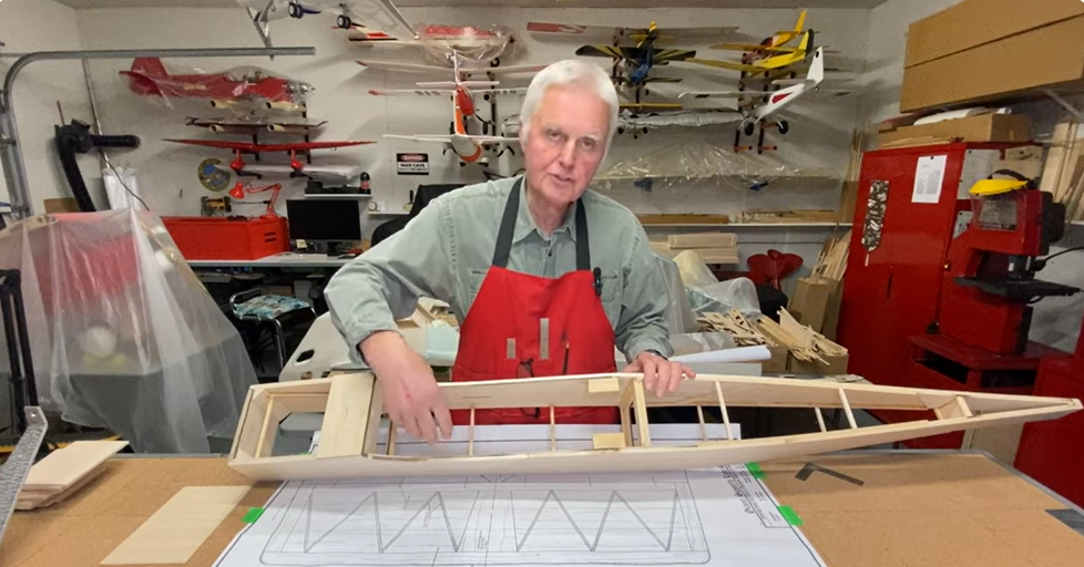
So now that we’ve set the stage for creating a 1/4-scale sport scale Sopwith Camel, let’s start building. When it comes to any project, I gather all my materials and supplies ahead of time, that includes ZAP adhesives, sandpaper, new X-Acto blades and so on. The first job is to remove all your laser-cut parts and check the plans so you can identify the pieces. Several parts look similar so be sure to mark them with a pen.
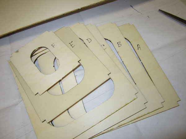
Fuselage formers are made of lite ply very basic and simple.
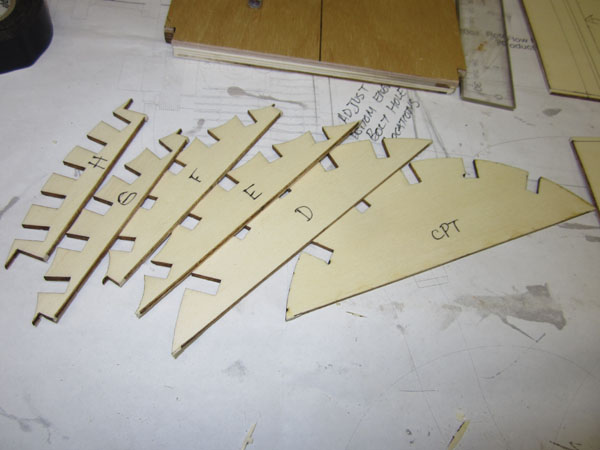
Top turtle deck formers (stringer supports are also made of lite-ply.

First step is to laminate the 4 layers of lite ply and birch plywood to form the 1/2 inch thick firewall. I used Zap 30 minute epoxy.
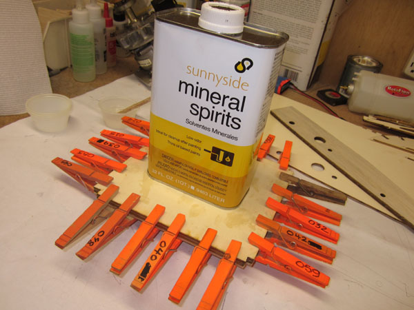
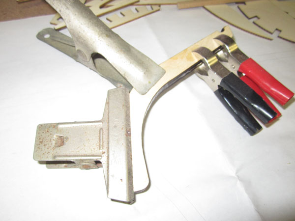
Lather up the layers with a thin even coat of epoxy and then clap together and add weight to the center. Make sure all the edges are even and flush. Also each layer’s grain direction is 90 degrees to the next one.
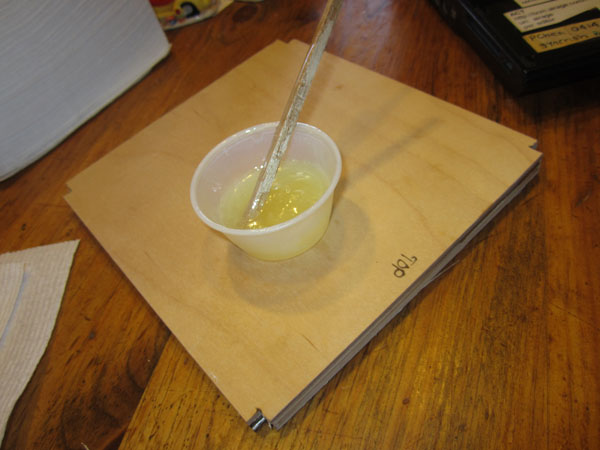
Here’s the finished laminated firewall. (Tech Note). I know it is simple, but when mixing a fairly large batch of epoxy, (more than an ounce at time,) use a digital scale. Place a container on it and zero out the reading. Add .5 oz. of part 1 and then add another .5oz of part 2. This gives a very accurate mix ratio. Works for other mix ratios also, 2 to 1 for example.
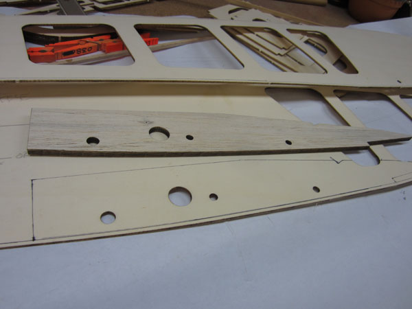
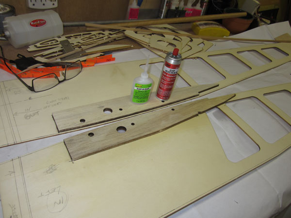
While I had the resin out, I laminated the two 3/16 inch birch plywood tail skid parts together as well.

A little sanding and it’s good to go.
Fuselage Sub-Structure
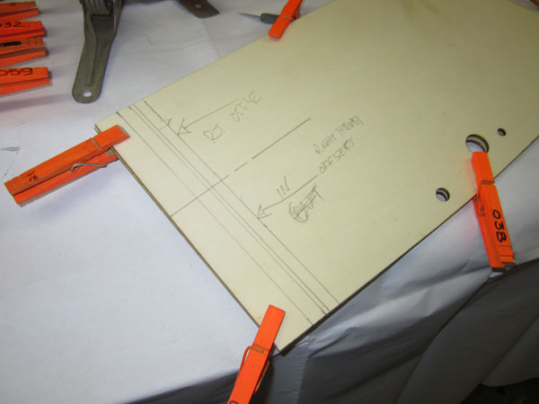
Clamp the two side pieces together and use the plans to transfer the positions of the formers and firewall. Here is the firewall position with its down thrust and side thrust offsets mark. Be sure to mark the inside and outside surfaces of the sides to avoid confusion later on.
You also have to mark the outer edges to allow for the laser cut top and bottom pieces. These will be flush to the edges and on the inside.
Position the lower wing support doubler and mark its location on the insides of both side pieces.
Remember to make a left and right hand (mirror image) when gluing parts to the fuselage sides.
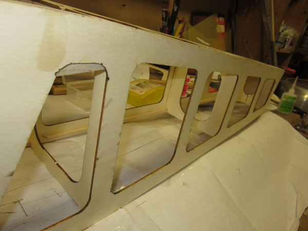
Now, using the edge guidelines, glue on the 1/4-inch square balsa longerons and verticals and diagonals.
At the tail end, the longerons go only to the last former location, not all the way to the rudder post.
Tack glue the first two formers into position as well as the firewall. Use just a small amount of glue here, and make sure they are square to the side.
On the other side, add the balsa verticals to match up to the formers just glued to the first side.
Now carefully bring the two sides together and tack glue into place. The formers should also have center marks drawn on for when the tail ends are joined.
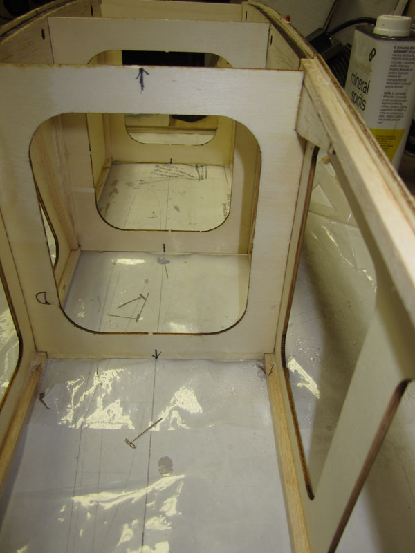
Also be sure to place some plans protector clear plastic over your drawings. See how the center marks align with the centerline drawn on the paper.
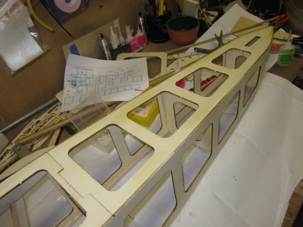
Continue adding the formers while keeping them aligned with the centerline guide.
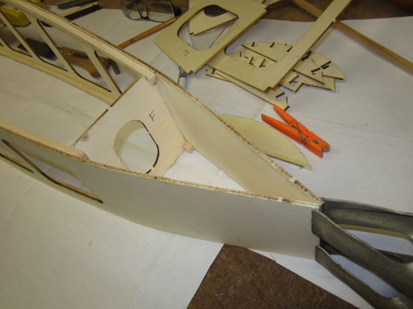
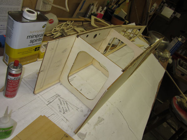
With the last former in place (all formers tack glued), pull the tail ends together and clamp as shown. Do not glue it yet. The bottom piece has to be fitted into place and the sides pulled tight against it before adding more glue.
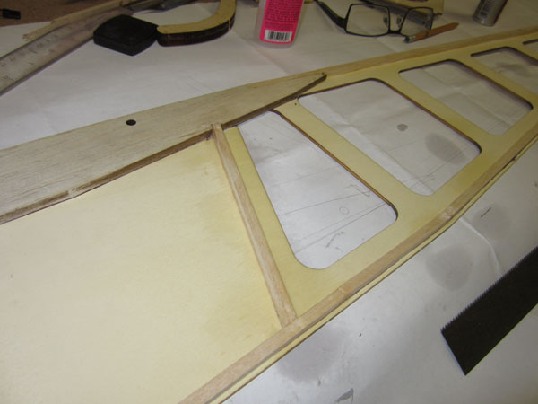
Here the bottom aft piece have been tack glued into place on the structure and the tail ends have been tack glued to it to form the unique shape of the Sopwith Camel’s fuselage tail structure.
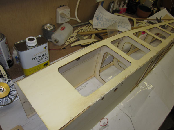
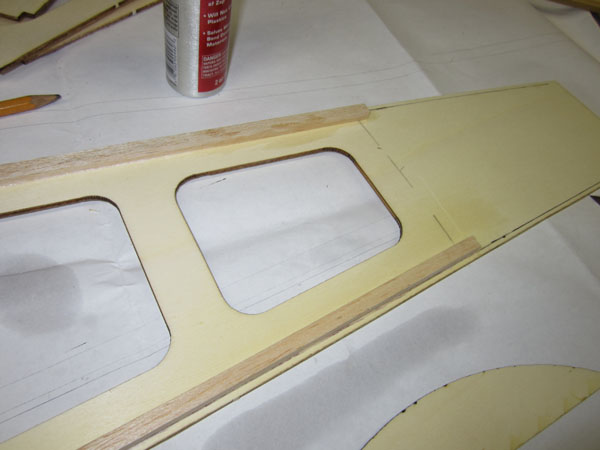
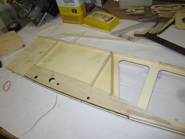
After the aft bottom piece is glued in place, position the front bottom piece and glue into place. The bottom pieces rest ontop of the longerons and should be flush with and tight against the side pieces. Notice that the landing gear block notches have not been cut or formed yet. Once I have it worked out, I will update the drawings to include the details so you won’t have to form them with a razor saw.
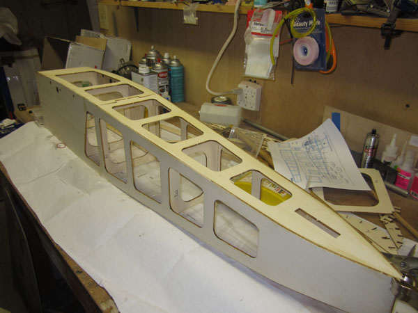
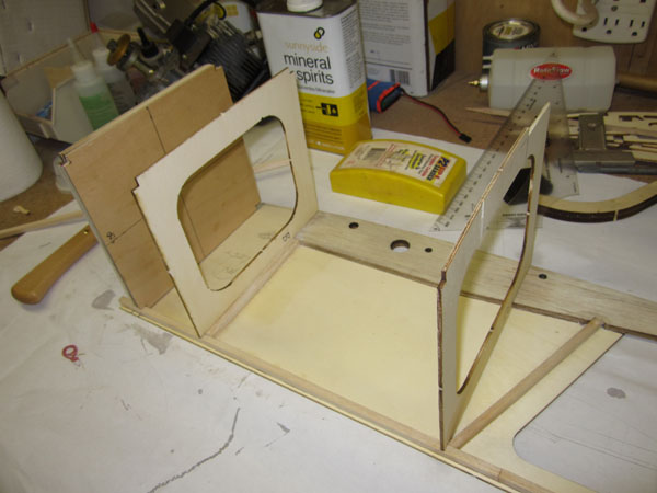
Here’s the assembled structure, after about 30 minutes of work time. Pretty simple and perfectly straight without much effort.
Happiness is a straight fuselage.
Next time we’ll add the top fuselage pieces, add some more verticals and diagonal balsa sticks and start setting up the engine on the firewall so it can be installed.
As a reminder, a good build depends on good quality parts. All the laser-cut wood for my Camel project came from Trillium Balsa (www.trilliumbalsa.com). It’s of excellent quality.
Until next time, stay tuned!
To see part 1 use the link: https://www.modelairplanenews.com/blog/2014/01/27/workshop-build-along-scratch-built-sopwith-camel/


How do I get the plans and layout of the structure to cut for frames and ribs
or Part 1 to start late
Hi Michael. the link to part 1 is above. But this is simply an update of my project. People can build in what ever way they want. usually I like to start with the tail feathers to warm up, but I am finishing up my Fokker Triplane at the moment for the WRAM show next weekend. The links for the drawings are above also so you can download them and print them if you like at a print shop. Stay tuned.
There are no lazer cut parts in a “Scratch build” Title is misleading. This is a “Kitbuild” unless you hand cut EVERYTHING! However, I must say that in this era of ARF instant planes, any build is refreshing to see. Keep up the good work.
LOL! Ha ha, I am not sure where your definition comes from. But thanks for the “encouragement” I have well over 100 hours invested in the CAD drawing by itself. This build will reveal any mistakes, so I can correct them in the plans.
HI Gerry
Just found this and I am impressed ! congratulations for having the balls to start this and go through with it….
I am making a simple biplane lamp to scale , and it seems I will have to prepare the CAD drawings myself ( i plan to use Autocad ) ..
However, I was wondering if you have the measurements for the fueslage height and width at the different points ….
all i have is info on wingspan and overall length
thanks in advance !
Do you accept manuscripts? I completed s build on a Ford Flivver 1/5 scale from plans and using a short kit.