This weekend was pretty productive as I now have the tail surfaces finished and installed. These were made removable for maintenance and for access to the tailskid’s suspension bungee setup.

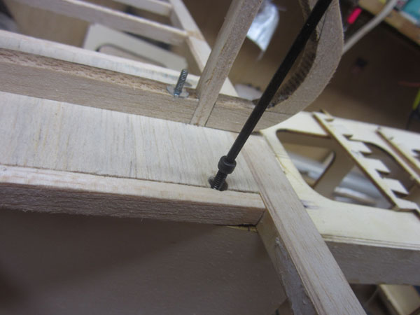
Under the horizontal stabilizer base, I glued 1/4-inch balsa cross pieces and installed 4-40 blind nuts in four locations matching holes drilled into the stabilizer.
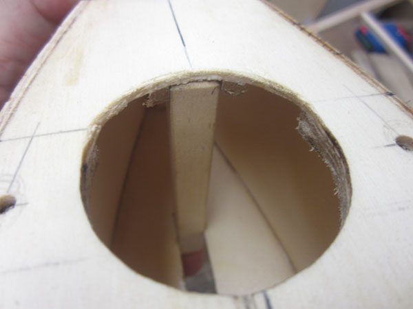
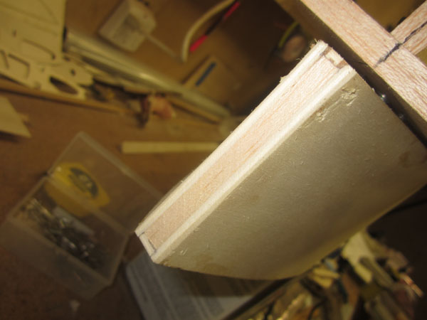
Looking through the large access opening you can see the vertical hardwood tailskid support post. It fits into a pocket I glued under the base plate for the stabilizer.
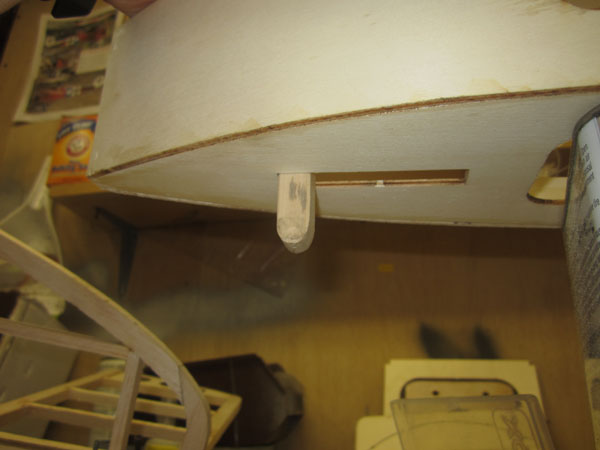
The bottom of the support post exits at the aft end of the tailskid slot in the bottom of the fuselage.
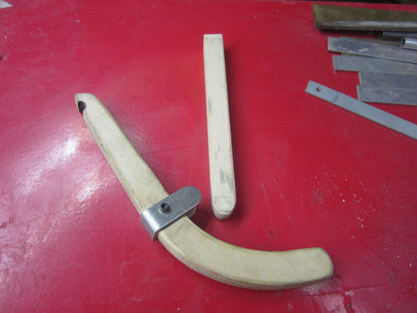
Here’s the basic layout for the tailskid. A hook in the post will anchor the bungee to pull the skid back.
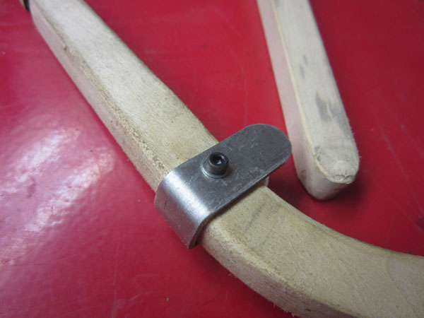
I used 1/16-inch aluminum for the pilot bracket. Here it is attached with a 2-56 bolt. The skid will be attached to the bottom of the post with another 2-56 bolt and a brass bushing.

Here you see the bottom of the stabilizer plywood center plate. The four holes to attach the stabilizer to the fuselage have the bolts in them, and the two center screw heads and washers are for the vertical fin attachment.
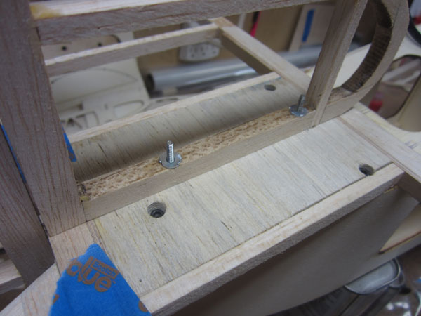
Here you see the vertical fin is screwed into place. The 2-56 blind nuts are just small enough to clear the covering. The openings in the base clear the fin attachment screw heads.
The stabilizer is secured in place with four 4-40 socket head bolts. I use a long hex driver to clear the vertical fin.
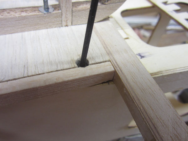
Tighten down, the bolt head is out of sight in the recess I cut over the bolt hole with a sharpened 1/4-inch brass tube. Neat and clean appearance.
The rudder tailpost is shown here. It is filled with edge-shaped balsa about an inch deep to make good hinge pocket slots.
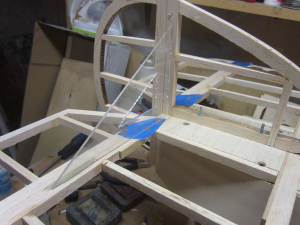
If the vertical fin is not square to the horizontal stabilizer, the bottom surface of the fin needs to sanded so it sets square when the screws are tightened.
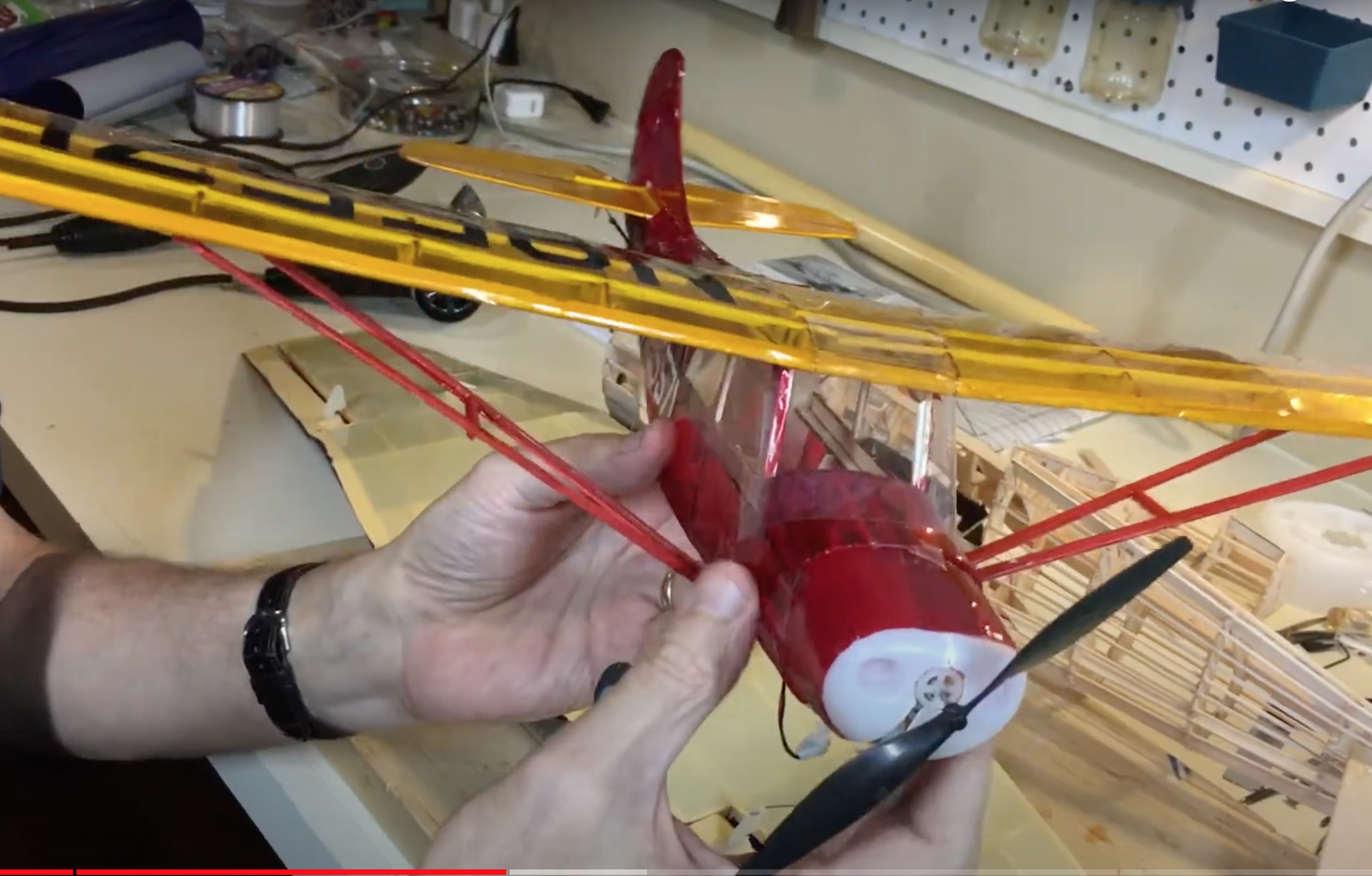
Here the tail feathers are setting in place. All the screw locations are perfect and the setup makes the tail easy to remove. Rigging wires will provide plenty of strength and will require only the bottom four to be removed from the fuselage for the tail to come off in one piece. The hinges have yet to be installed.
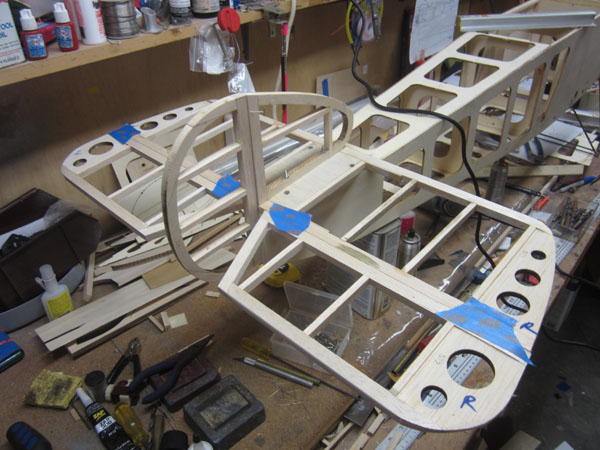
Fuselage Formers
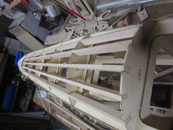
With the of the leading edge of the stabilizer determined, it is time to work on the turtledeck.
Here you see the aft most turtledeck former. It is glued into a slot that I cut into the turtledeck base. The LE of the Stabilizer butts up against the former.
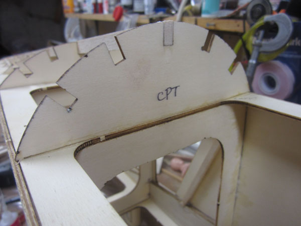
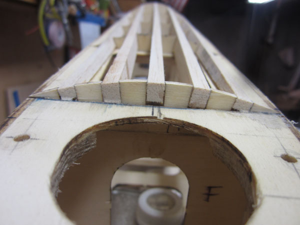
The next step is to lineup and center the aft cockpit former and glue it in place so the center stinger is straight.
Each of the mid formers are then positioned under the center stringer so they support but do not bow the stringer up. Once the location is determined, the formers are glued into place.

Looks pretty straight to me.
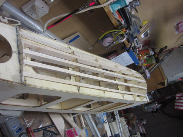
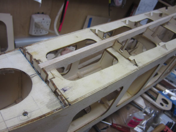
Here the rest of the stringers have been glued into place. The middle formers are scalloped so they do not touch the covering material.
The aft ends are tapered to set flush with the top of the aft former.
I am pleased with how straight the stringers tuned out.
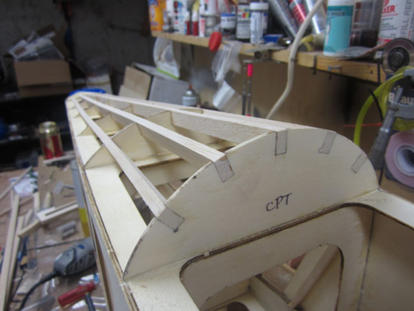
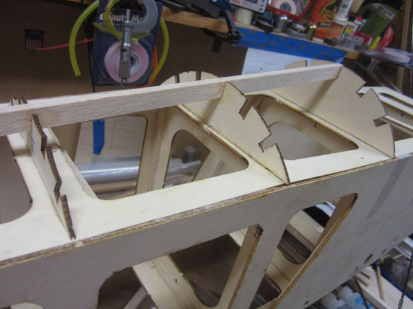
The first two formers are full profile so the plywood panel sections have something to be glued to after the turtledeck has been covered with cloth.
That’s it for now.
To see the next installment (Part 9) of the Build-Along series, click the link: https://www.modelairplanenews.com/blog/2014/07/21/workshop-build-along-sopwith-camel-part-9-gun-hump-and-cheek-fairings/
To see part 7 of the Build-Along series, click the link: https://www.modelairplanenews.com/blog/2014/06/25/workshop-build-along-sopwith-camel-part-7-tail-surfaces/