
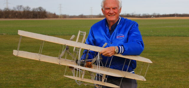
About two decades ago enthusiasm was building within the aviation community with the anticipation for the celebrations to come for the 100th anniversary of the advent of controlled human flight. This is the story of how I came to design, build, and fly a 1/10-scale model of the 1905 Wright Flyer.
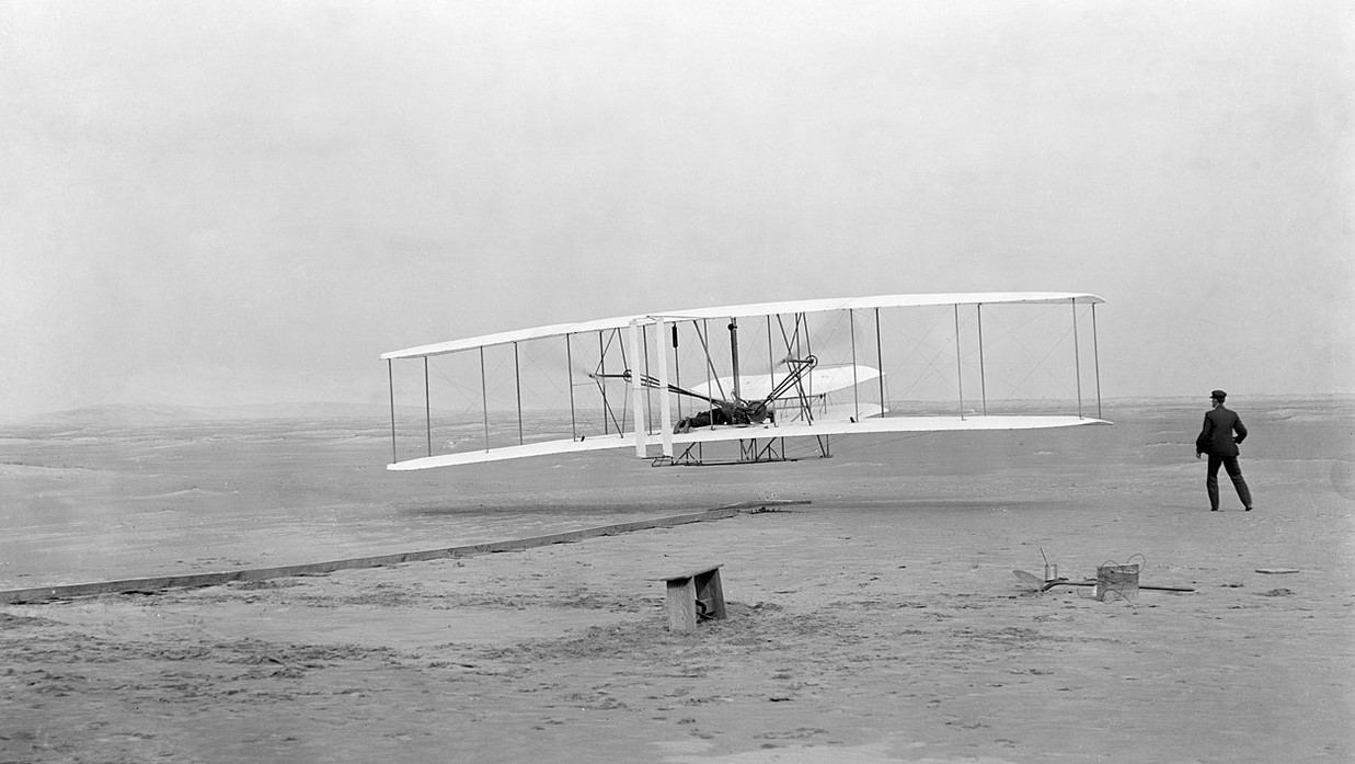
Time was running out for Wilbur and Orville Wright before their return trip back home to Dayton, Ohio. In less than ideal conditions they made the decision to give their first flights a try. So on December 17, 1903 at Kitty Hawk on the sand dunes in North Carolina, the Wright Brothers made four flights. Orville won the coin toss and took off in head winds of 27 mph in near freezing temperatures for the first of four attempts. His flight lasted 12 seconds and he traveled 120 feet. On the fourth and last flight of the day, Wilbur traveled 852 feet in 59 seconds. With their projected airspeed of 34 mph, his ground speed was 6.8 mph.
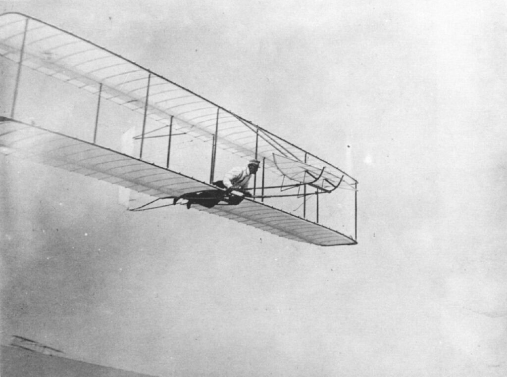
Wright brothers’ 1902 glider.
Some naysayers claim that they were not official flights as they took off going downhill, sliding on a rail and into a head wind. When an F-14 is catapulted from the deck of an aircraft carrier by mechanical means to sustained flight, I think we can cut the brothers a little slack. Wilbur’s last flight of 59 seconds traveling 852 feet using three axis control at 6.8 mph at an average height of 10 feet. I think any reasonable person would consider that controlled flight. The 1903 design was far from perfect with short coupled control surfaces with minimum surface areas of the canard and vertical rudder. The center of gravity needed some tweaking also. These shortcomings were later corrected with their 1904 and 1905 redesigns. I think they both had their hands more that full on that memorable day. Their racing skills on their own designed bicycles I believe came into play with more than average athletic abilities and motor skills.
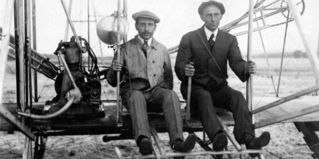
The Wright brothers
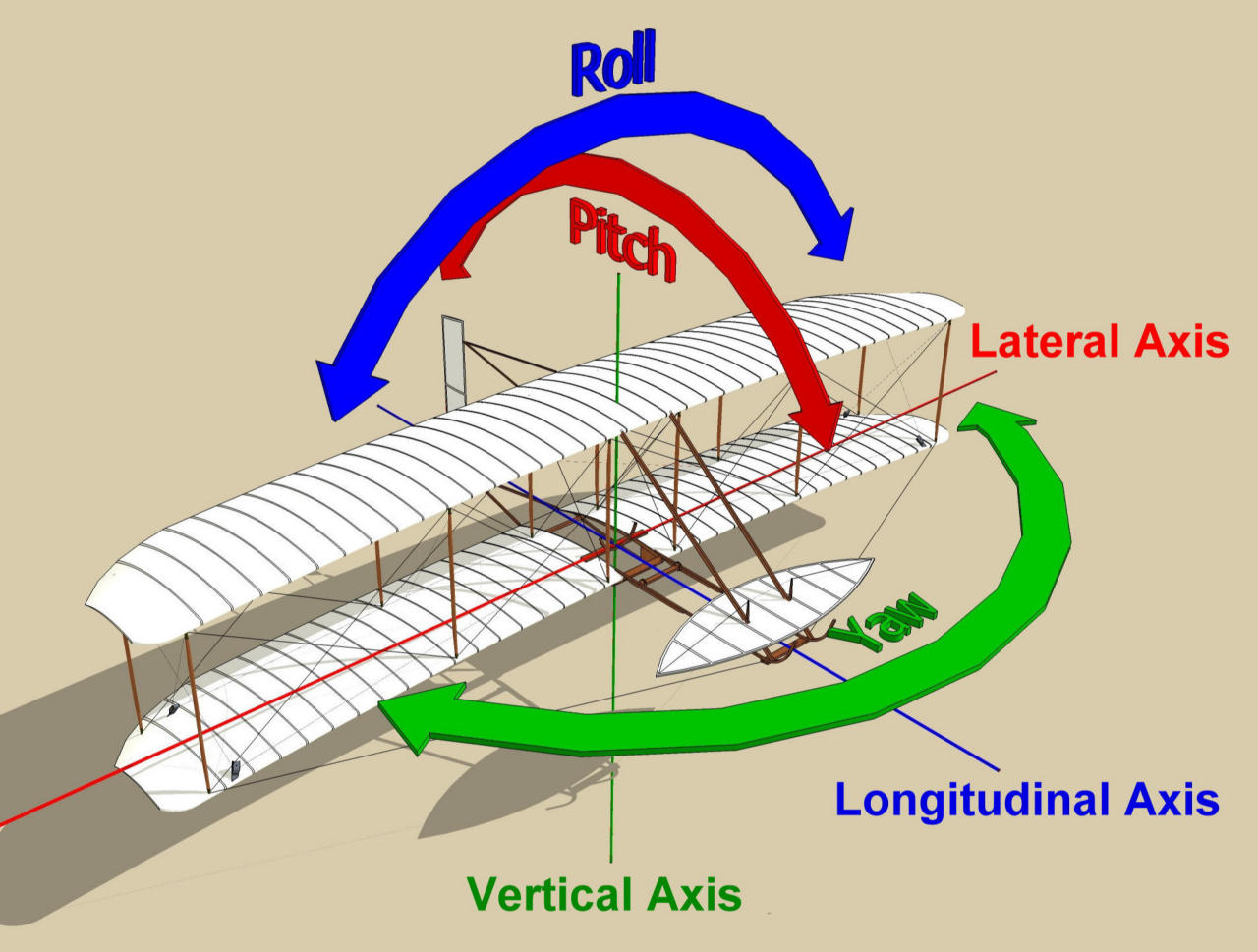
History is well written that there are many others that claimed they flew prior to the brothers. My research has not led me to believe these accounts are plausible for many reasons. For one, lack of photo evidence. Also have you seen some of these photographs? Yes, there are many written accounts of observers that claim to have witnessed flights. I don’t remember any of these accounts that claimed three axis control. Maybe I missed them. The brothers used three axis control, roll, pitch and yaw on all their gliders and powered aircraft. Is three axis control needed for successful flight? Not necessarily. We modelers know that success flight on our models can be achieved with yaw only. My first RC model that I designed and flew when 15 years old had only rudder control. A wing with high dihedral gives sufficient stability in roll control without the use of ailerons or wing warping that was used by the brothers. The photos of those aircraft that claimed flight before the Wrights show little signs of any roll, pitch or yaw control.
So my interest was piqued. As a modeler designing RC aircraft since the age of 15, with the upcoming anniversary of 100 years of flight a decision was made, I thought I should look into the building of a true scale RC flying model of a Wright brothers airplane.
A small library of books on the Wright brothers and their many flying machines was acquired. And the research began. What an enjoyable time spent reading. I think my favorite book was written by Tom Crouch entitled “The Bishop’s Boys.” He is/was? the Senior Curator at the Smithsonian Institution in Washington DC. He was born just a few miles west of my home in Springfield Ohio in the village of Chrystal Lakes. A small factoid of interest, Mr. Crouch and my wife graduated from the very same Tecumseh High School. I had the privilege of attending a lecture of Mr. Crouch several years ago. As I remember I think I shook his hand and complemented him on his book. I didn’t wash that hand for several days!
So if this Wright brothers’ airplane design and construction was to begin, the question was which airplane and what scale. From my research it was apparent that the 1903 was not to be considered if a flyable airplane would be possible. Of course I suppose gyros could be utilized but no thank you. The brothers considered the 1905 to be the “First Practicable Airplane.” With it they could fly figure eights, circles and land back at the place of their accent. So the 1905 was chosen. Electric power was coming into vogue back when this project was started in 2002. Next what scale? 1/10 was chosen. Scale drawings were required so The Smithsonian was contacted to see if any were available. It so happens they were. Apparently when the original 1905 was to be ‘restored’ for the Carillion Park in Dayton Ohio, drawings were commissioned. Orville was available to oversee these drawings. So drawings were ordered and produced. They were very extensive and detailed. Orville even signed one of the pages and dated it with his approval of one particular detail. I couldn’t believe it.
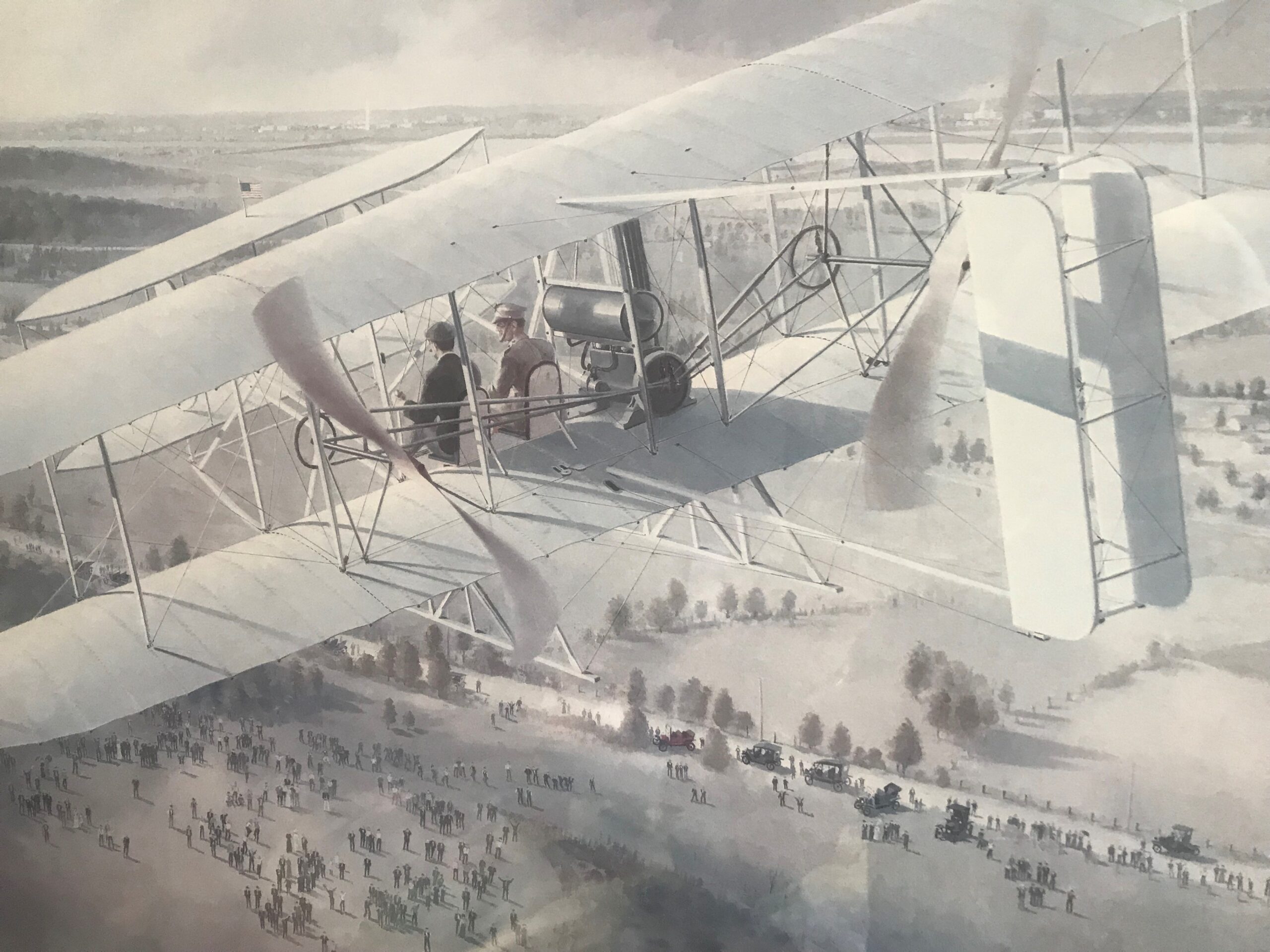
A photo of the author’s copy of a numbered lithograph by Keith Davis of the 1909 Flyer that was flown to secure the purchase of the first military airplane by the US government.
It has been said that the journey is more interesting than the reaching of your destination. In this case, I think that we must relieve their journey to better understand how their final destination was reached. The brothers traveled to the sandy beaches in North Carolina starting in 1900 with gliders. They continued their travels there in 1901 and 1902 before deciding that they had learned enough to attach an engine to a flying machine. If successful they would achieve successful powered human flight.
The brothers developed an interest in human flight at an early age. Their father, Bishop Milton Wright, traveled to the many United Brethren churches under his leadership. On one occasion in 1878, he returned from a trip with a little toy helicopter designed by French aeronautical experimenter Alphonse Penaud. At the time Wilbur was eleven and Orville seven. It was a stick with a four-blade rotor fixed to the top was set in a hollow spindle held by hand. When a sting wrapped around the stick and pulled the rotor rose out of the spindle. Octave Chanute who became a great friend with the Wright family over many years said, “This helicopter the best of its kind.” This type of toy dated back to the fourteenth century. The Brothers said this fueled their interest in flight.
In 1899 the brothers became seriously interested in the problem of human flight. Wilbur took the lead and wrote to the Smithsonian Institution asking for the best books on this subject. He mentioned his previous experiments in making models of bats and in the style of Cayle’s and Penaud’s machines Wilbur said and I quote, “My observations since have convinced me more firmly that human flight is possible and practicable.” After some delay the Institution did send boundless information including information from Octave Chanute and Samuel Langley.
With this information in hand, the brothers decided to design and build gliders which they were to test on the sand dunes at Kitty Hawk in North Carolina. They did this over a period of three years, 1900 through 1902. They made many flights and observations modifying their gliders each year.
At this point I would like to remind the readers that from the beginning the brothers used three axis control on all of their flying machines. Roll, wing warping for them, ailerons for those after, yaw, rudder control and then pitch, canards for the brothers and elevators for those designers coming after.
I think those that claimed controlled flight before the Wright Brothers did not use three axis control. I may be wrong and I am sure the fact checkers will be pretty busy looking into this subject.
After returning to Dayton Ohio after the tests in 1901, they decided they needed to build a wind tunnel to test airfoils and more. They completed the world’s first wind tunnel on November 22, 1901 and began their tests. They made over 150 small model airfoils, camber of 1 in 20 and aspect ratio 6 to 1, 6 inches span with 1 inch chord. They discovered that the best location for the peak of the chord to be 1/4 the distance from the leading edge of the airfoil. They were so excited with the results of their tests that they could hardly wait for a new day to begin so they could continue and build on with this new found information.
With the now redesign for their new 1902 glider, they traveled back to the sand dunes. They were able to make longer glides than in the two preceding years. Now it was time to design a larger Flyer with which to attach a motor. So the next step in their great adventure was to move forward to the ultimate success of their great dream.
-
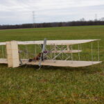
- Wayne Ulery’s 1/10-scale 1905 Wright Flyer
-
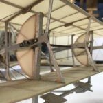
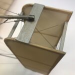
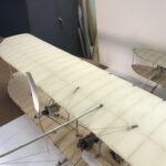
- The two blinkers were placed between the upper and lower canards.
-
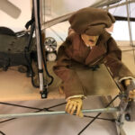
- Note the pilot figure’s hands on the control levers for the pitch control, canard, and rudder, and his hips on the wing-warping sliding tray.
-
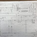
- Rudder drawing
-
- Rudder attachment and pivot point.
-
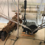
- The pilot would move his hips from left to right on the sliding tray to control the wing warping.
-
- Two electric Hacker B20 31S motors geared 4:1 and uses two Lithium 1200mAh packs power the Flyer.
-
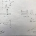
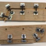
- Hip rest slide, left / right for wing warping and foot rest, from Smithsonian drawings.
-
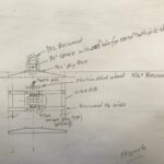
- Magneto drawing.
-
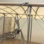
- The rigging guy wires are fishing line, specifically Spiderwire 50-lb. test. The chain guides are soda straws.
-
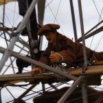
- The balsa pilot figure has the head and hands of an action figure.
-
- Fixture to assemble parts for connection from landing skids to canards.
We modelers that like to design our own models and build from scratch have many decisions to make before we start. Are we wishing a sail plane which is best with high aspect wing ratio for soaring? Or maybe a trainer or even an aerobatic aircraft with lower wing aspect ratios.
More questions. How large should the horizontal stab be? How much area compared to the wing area? How far back from the wing should the horizontal stab be located. Where should the CG be?
My questions were partially answered by a fellow WORKS club member back in the late ‘50s I guess. John Chuprun (sp?) was an aeronautical engineer that was employed at the nearby WPAFB. During one of our meetings, I asked him these important questions. By the way, the club president presiding over the meeting called us out several times for taking. I was embarrassed … a little.
Anyway he said it’s pretty simple. The horizontal stab area should 20 to 25% of the wing area. It should be placed anywhere from 20 to 25% of the wings mean aerodynamic chord (mac) from ¼ chord of the MAC of the wing to the 1/4 of the horizontal stab’s MAC. If you placed the stab further back the stab area could be smaller, similarly moving the stab any closer it would have to have more area. Perhaps the most important question I asked to which he answered was about (CG) of the airplane. As you modelers all know, the CG is determined by balancing the fore and aft balance by balancing the plane by lifting it with your fingers under the wing until it balances level. Then measure the distance of the balance point from the leading edge of the wing. Presto you have located the CG. How to find the MAC of any wing, swept, straight, tapered etc. was my next question. He said real simple and he proceeded to make a simple drawing which I used on all of my model designs.
By now you are asking what all of this has to do with the brothers and the design of their Flyers. Also I had some questions about the placement of the CG on my 1/10 scale 1905.
Well sit back and relax and we will talk about what happened when they returned from Kitty Hawk after the first four flights of the 1903 Flyer and the beginning of their changes to the 1904 Flyer.
1903 Wright Flyer
I just talked about the CG of any airplane which holds true for model or full size. The 1903 had monstrous pitching problems. Recollections of those few that witnessed the first four flights noted that it was moving up and down like the waves of the ocean. We now know that the CG was too far aft. From my research I do not believe that they were fully aware of the pitching problem with this rearward CG. One of the first changes they made to the 1904 exacerbated the problem.
To be honest I don’t know how Wilbur ever completed the 852 feet in 59 seconds with our crashing. An amazing feat in my humble opinion.
So now back in Dayton they constructed a new Flyer based on the 1903 flyer. They had their mechanic, Charlie Taylor, build a new engine with increased cylinder bore which increased its horsepower from 12 to 18. They also redesigned the rudders.
The test flights were made in a 100-acre cow pasture eight miles east of Dayton owned by a Dayton banker Torrence Huffman. Without the winds at Kitty Hawk, they devised a catapult system to launch them into the air. Once airborne they still had the same pitching problems so they changed the location of the fuel tank and radiator from the front wing struts to the reward struts. They also moved the engine aft to also move the aircraft CG aft. This only made the pitching problem worse.
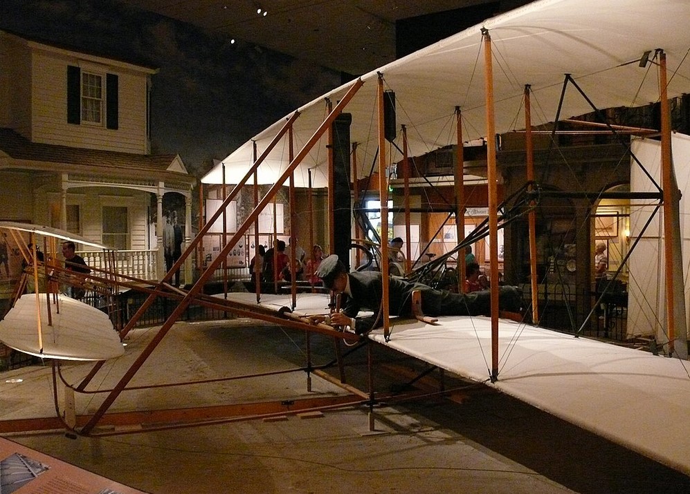
Wright Flyer in the National Air & Space Museum
At this point in our conversation please enter A. I. Root. (Amos Ivey Root) (1839-1923) herein after referred to as Root. He founded a company that sold supplies and equipment for bee keeping. He also published the journal Gleanings in Bee Culture. So in 1904 when he heard of the brothers in Dayton that their investigation of the soaring of birds had led them to building gliding machines to which they would attached a motor. Root drove the 200 miles from Medina Ohio to see what was going on. You may asked what car he had in 1904 to accomplish this trip. Who of us could imagine the condition of the roads back then? Well, how about a 1903 Oldsmobile. At this point my interest in Root grew large. Root became friends with the brothers and wrote extensively in his Gleanings in Bee Culture journal of January 1, 1905 of his great adventures in 1904. References to his observations will be mentioned as this writing goes forward. I recommend to those reading this article, look up his journal on the internet. One of the most descripted and fascinating things ever written about the brothers.
Back to the pitching problem. The brothers now realized that the CG of their flyer must be moved forward rather than aft.
The solution was to add 50 pounds of cast iron to the front of the flyer under the lower canard location.
I would like to mention the experience with the CG on my 1/10 scale 1905 Flyer. The wing chord is 7.75 inches, the flying weight is 31 ounces. I didn’t want to add cast iron weight to attain the proper CG so I mounted the lithium batteries which weighed 3.75 ounces under the lower of the two canards. The CG is actually on the leading edge of the wings or about one quarter inch ahead. When you watch the video on you tube, you can see that the flyer is very stable with no apparent problems and little positive angle of attack on the canards during flight. When Quique Somenzini (World Champion F3A pilot) landed, I asked how the flight went. He said it was not an easy airplane to fly although you would never notice any problems watching the video. You can check it out here:
To exactly quote Root, “to make the matter short, it was my privilege, on the 20th day of September, 1904, to see the first successful trip of an airship, without a balloon to sustain it, that the world has ever made, that is, to turn the corners and come back to the starting point.”
Additional quotes by Root, “Since the above was written, they have succeeding in making four complete circles without alighting, each circle passing the starting point. These circles are nearly a mile in circumference each; and the last made Dec. 1. The longest flight took only five minutes and four seconds by the watch. On both of these trips seventy pounds instead of fifty of cast iron was carried on the “nose”.”
Please allow me to add one more exact quote by Root. “ Imagine a locomotive that has left its track, and is climbing up in the air right toward you—a locomotive without any wheels, we will say, but with white wings that spread 20 feet each way, coming right toward you with a tremendous flap of its propellers, and you will have something of what I saw”. It is emotional for me as I write and read this quote again and again. You can see it was emotional for A. I. Root as well. Impossible to be able to witness such a world changing event … and he was there.
A. I. Root was perhaps the first witness to the brothers’ flight successes in 1904 at Huffman prairie to write about man’s first controlled flight. A turning point in history. You can see why I was inspired to take on the challenge of designing, building and flying the Wright’s 1905 Flyer, which the brothers called “The first practical airplane.”
After the brothers’ success during the flying season of 1904, they put their heads together to decide what improvements could be made on their next “Flyer”. They made some significant plan form modifications. This resulted in solving the pitching problems.
They almost doubled the size of elevator (in front) and rudder (in back) and moved them about twice the distance from the wings. They added two fixed vertical vanes (called “blinkers”) between the elevators to serve as stabilizers and help prevent the Flyer’s tendency to slip or slide sideways in a turn. They adjusted the rigging to give the wings a very slight dihedral and counter the airplane’s tendency to roll. They disconnected the rudder control of the rebuilt Flyer III from the wing warp control — as they would in all future aircraft — placing it on a separate control handle. (The wing warp — roll – and rudder — yaw — controls had been interconnected in the previous flyers. (Author’s note: I took the above paragraph directly from a website, my apologies.)
If you look at the top view of the 1902 and 1903 flyers and compare them to the 1905, you as a modeler can see that the 1905 looks like a flying machine that could actually fly. Not so much the previous two as they were so short coupled.
As mentioned before the brothers used a catapult system to get airborne. Again I copied the next paragraph from info available on the internet as I thought the readers might be interested.
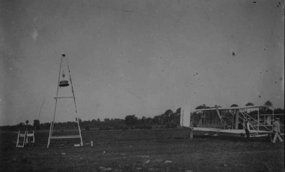
The Wright launching catapult consisted of a derrick (1) and a launching rail (2). The derrick suspended a heavy weight (3) about 20 feet (6 meters) above the ground. A rope ran from a simple pulley (4) at the top of the weight through a compound pulley (5) at the top of the derrick, then down through the simple pulley and back up through the compound pulley. From there it ran down to a simple pulley (6) at the bottom of the derrick, then under the rail to another simple pulley (7) about 65-75 feet (20-23 meters) out along the rail. From there, it ran back to a hook on a tow bar at the front of the airplane (not shown). The airplane rested on a two-wheel truck (8) which rested on the rail. When the weight dropped, the rope pulled the airplane and the truck along the rail. As the airplane took off, the rope slipped off the tow bar hook and the truck ran off the rail’s end.
In order for my 1905 scale model to reached flying I made a little three wheel dolly on which the flyer rested. After flying speed was reached, the dolly scattered off to the side. If you look closely you can see this in the YouTube video.
At this point information on my 1905 flyer ends. However, the Wright story continues on for many years. A couple of examples of many possible.
The brothers had a continuing patent dispute with Glenn Curtiss over their control system over many years. Wilbur applied for the patent in 1906 which was granted. Wilbur warned Curtiss in 1908 about infringing on their rights. Then on January 13, 1914, the courts decided against Curtiss. Wilbur carried this fight and according to his father Bishop Milton Wight it had a profound effect on Wilbur’s heath. Much of Wilbur’s time was spent defending their patent over what appears to be eight years.
Wilbur made his first flight in Europe in France on August 8, 1908. Subsequently he gave rides to dignitaries and royalty is several European countries. At this point the pilot and passenger were sitting upright on the front of the lower wing with improved control mechanisms. A side note. Before Wilbur’s trips to Europe the newspapers had heard of the bicycle mechanics in America and their flying machines. Some headlines read, “Flyers or Liars.”
This one last story you may find hard to believe but it is true. If involves my good modeling friend Jim Cline. Years ago his father lived down the street from the brothers in Dayton Ohio. One of their later airplanes was the 1913 Aeroboat which they flew off the Miami River in Dayton. After they were finished with the airplane they gave some of the wooden parts to Jim’s father. Jim acquired them from his father. Jim showed them to me many years ago. I was so bold as to ask Jim if he would be interested in parting with them. This conversation went on for many years and finally he agreed. One was a longeron about eight feet in length that went from the wing to the horizontal stab. Jim said his mother used it as a clothes line support pole in their back years for many years. We both had a good laugh about that.
About that time I became friends with Nick Engler. When he heard of the parts I had, he wanted to restore the 1913 Aero boat. He claimed that if he had just one part of the original he could call his build a restoration so I gave all of the parts I had to him. I don’t believe he ever started the project. By the way, Nick built the 1903 Flyer replica that is hanging in the lobby of the Dayton International airport. You can find more on Nick’s Wright Brothers experiences, which are many, on this website. Cut and paste. www.wright-brothers.org
I think my ramblings should end. I could go on and on with many thoughts and stories regarding the brothers. I hope you have enjoyed my musings. The 1/10-scale 1905 Flyer was a challenging and fun filling adventure. Don’t forget to watch the model in flight.
By WAYNE ULERY | PHOTOS BY JEFF HOLSINGER
ABOUT THE AUTHOR
Is it possible that a person’s interest in certain activities with an unquenchable passion be embedded in their DNA? As an example let’s talk about all things aeronautical.
Wayne’s father took flying lessons in the 1930s. His brother and two uncles flew. A first cousin was a corporate pilot for Dow Chemical. A grandson has just garnered his commercial ratings with a degree in Aviation from BGSU. He himself obtained his solo license in 1955 at the age of nineteen in a J-3 Cub.
But his aeronautical interests soon shifted and found their home in modeling, specifically in designing and building radio controlled aerobatic airplanes.
He designed his first RC model in 1951 at the age of 15. It was powered by a McCoy .15. The transmitter had one button to control the rudder only airplane. The rudder was operated by a rubber powered escapement, one right, two left. The Aerotrol receiver had one gas radio tube. No transistors yet. All batteries were dry. When it was out of fuel, it landed. On its maiden flight it flew away thanks to a cold solder joint that was made when extending the receiver antenna. What does a fifteen year old know about soldering? Yes it was recovered but that is another very interesting story, too long for here.
Yes, he enjoyed flying and even competing at the National level with his 1/6-scale Smog Hog. It was flown with a five-channel reeds radio and a K&B 45.
At this same contest he couldn’t believe the building and flying talents of Harold DeBolt with his bi-plane and Bob Dunham with his low wing Astro-Hog. Attending were many other pioneers in the fledging field of model aerobatics.
In the early sixties he designed a mid-wing monoplane which was his first composite fiberglass model. His good friend Don Lowe, former president of the AMA flew it to fifth place at the Nationals.
Over many years two designs emerged for F3A competition, both used nationally and in World Championships. The EU-1 and the Vortex flown exclusively by his good friend Dean Koger. Dean flew the EU-1 at the World Championships in South Africa in 1979 with the USA winning team honors. The Vortex was unique as he designed a belt reduction unit for the engine with a 2.25 to 1 reduction ratio. This allowed for the use of a larger diameter prop turning at lower rpm to reduce noise levels. The larger diameter hand crafted modified wooden prop also gave great vertical power. The pitch was increased. It was thinned to reduce drag and covered with Carbon fiber clothe to strengthen. Dean flew this Vortex at the 1989 World Championships in Virginia Beach, Virginia.
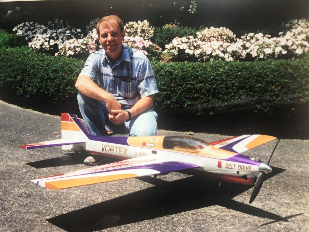
Vortex airplane with Dean Koger with the 2.25 belt reduction drive. Dean flew it at the World Championships at Virginia Beach in 1989.
Enter the Tournament of Championships (TOC) in Las Vegas. This was an invitation only event to the best twenty F3A aerobatic pilots from all over the world to compete for cash prizes. Ten from the USA and 10 from around the world. This event is claimed to have ushered in the large scale aerobatic airplanes so popular today. This was the premier event in all of model aerobatic competition. The last year of its existence first place prize winnings was $50,000.
So Wayne drew plans for designs, the Laser 200 and the Giles 200. They were flown by many competitors over many years at the T.O.C. Ten of the 20 planes flown at the 1982 TOC were the author’s 1/3-scale Laser 200.
The author, as noted in this publication, became interested in the Wright Brothers and their Flyers when the 100th anniversary of the invention of flight approached in 2000. He hopes that you enjoy his and the brothers’ journeys with their 1905 Flyers.


Great article, Wayne! Really enjoyed it! So gkad you’re still into modeling! All the best. Your friend in Kansas City, Jon Britt
Thanks Jonathan, really some great memories I have with you and so many others over many years.
Great article. The only thing I’m having a problem with is the description of tail moment..
Place the stab “anywhere from 20 to 25% of the wings mean aerodynamic chord (mac) from ¼ chord of the MAC of the wing to the 1/4 of the horizontal stab’s MAC.”
Ive always used chords lengths to determine moment arm , but Ive gone 2 to 3 wing MAC as the distance from the CG to 25% stab MAC.
Yes, I didn’t do a very good job of explaining it. Sorry. If we could sit down and with a pencil and pad it would be much easier for me. If you are ever in the area, Springfield Ohio, we can have coffee and have a good conversation.
Let me add Four tidbits to the Wright saga;
1…The sister Katherine was indispensable. She knew fabrics and also did the sewing for the covering.
2…One of the brothers held the soaring record of 9 minutes with one of their gliders.
3…The early gliders were nearly uncontrollable because the simple bent wood ribs flexed too much. Chanute taught the Wrights how to make rigid design ribs.
4…In 1905 the Wrights were about to give up because too many flights ended up crashing at the Dayton field. Wing tip stalls only got worse with aileron correction. On one last flight, the brother encountered the tip stall but this time applied full opposite rudder….this swung the lower wing forward and the extra tip air speed lifted the wing to level. The flight continued normally. The brother rushed back to the shop and explained what he did and how it solved the problem.
Great tidbits and you are correct. So many interesting stories out there in many books written about the subject. Thanks, Wayne
Have held the full size Wright Flyer with Hillman Imp Engine at Narromine Australia for engine run up. Subsequently flown by Colin Paye whoe restored a Mk 8 Spitfire that flies from Temora NSW.
The original Wright Flyer was on display in the science Museum in London England until 1942 as the Smithsonian insisted that Langley was the first to make a controlled flight. Langley was secretary of the Smithsonian at that time. The US Navy gave Langley $50,000 to build his “Aerodrome”, the Wrights used $2,000 of their own money. Glen Curtis in 1914 with hindsight extensively modified the Aerodrome and “proved”it could have flown by making short uncontrolled hops in it.
Only when the Smithsonian recanted that assertion did Orville Wright finally agree that the flyer should be move to the Smithsonian.
To this day, in the hall where the Flyer is displayed, is an emphatic statement that that Langley’s Aerodrome could never have flown. Modern visitors probably wonder why they make such a strong statement about something that didn’t fly!
You are absolutely correct. You have stated the facts much better than I could have. I should have included this information in my article. In part the plaque at the Smithsonian with the 1903 flyer states in part, ‘man made free, controlled and sustained flight invented and built by Wilbur and Orville flown by them at Kitty Hawk December 17, 1903.