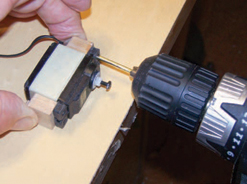
My sport-scale 1/5-scale Sopwith Triplane has a rather thin wing (though it’s thicker than scale at 1 inch at the aileron servo). A low-profile servo, such as Airtronics 94921 or Hitec 77BB, would fit with the shaft vertical, but I had standard ones on hand, so I went with them. I made an 1/8-inch-thick and 2 7/8-inch-wide plywood plate to fit between the ribs at the servo location and 2 1/2 inches long to go between the main spar and aileron spar. I glued a 3/8-inch-wide strip of 1/4-inch-thick plywood to the inside of the ribs so that I could mount the plate. Use a piece of scrap out of 1/8-inch-thick plywood as a guide to inset the mounts so that the servo plate is flush with the outside surface of the wing. Position the servo on the plate, and mark where the output arm will protrude. Keep the outside edge of the slot 1/2 inch in from the edge of the plate so that nothing will interfere when the plate is in place on the mounting strip. Drill 1/4-inch-diameter holes at each end of the slot, and cut between the holes with a hand-coping saw or power jigsaw. The Dremel jigsaw that I’ve had for years works well.
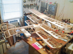
Building the Sopwith Triplane means that you have six aileron installations. I install my two aileron servos in the bottom wing and then drive the four others about them with slave rods. Keeping the servos in the bottom wing eliminates having to run servo leads up the cabane struts to the top wing.
You can mount the servos to the plates with aluminum angle or 3/8-inch-thick hardwood blocks. Because I always have maple on hand and a small, 8-inch-diameter-blade table saw, I made up some wood blocks as shown in the photo. Drill a 1/8-inch pilot hole and a 1/2-inch-diameter hole at one edge of the strip. The pilot hole makes it easier to drill from both sides, reducing the splintered breakout. Wrap the servo with three layers of masking tape to create a space around the servo after it has been mounted.
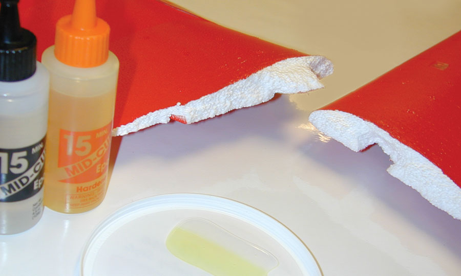
Place the servo and mounting blocks on a flat surface, and hold them in place. Spot transfer the servo holes to the blocks. I have made a simple tool for doing this, and it works every time. It’s simply a 3/32-inch-diameter drill inside a piece of 1/8-inch-outside-diameter brass tube. Cut the tube 1/8 inch shorter than the drill. Insert the cutting tip of the drill 1/2 inch into the tube. Coat the exposed drill with 5-minute epoxy, and push it through the tube until 3/32 inch of the tip is exposed (it should be free of epoxy). Let it cure.
The 1/8-inch tube won’t fit through a servo-mount eyelet, so its diameter will have to be reduced. Place the drill/tube assembly in an electric drill, and with it running, use a file to reduce the outside diameter until it will fit through the eyelet. I use a 3/32-inch-diameter drill for a no. 4-40 tap. This is a little smaller than the 0.099 inch my drill index calls for, but it creates a deeper thread in the wood.
Take the tape off the servo, and assemble the blocks to the servos. For ailerons, be sure to make a right and left; the flaps will be the same.
AILERONS 101
I remember back in the early days of RC when aileron servos (or should I say “servo!”?) were mounted in the center of the wing. Two pushrods operated strip ailerons, or they went to the outer-wing panels to a bellcrank and pushrod to barn-door ailerons. This was pretty much the standard installation. With larger models and relatively inexpensive servos, a servo on each control surface is now common. This is a better system, offering a number of advantages. The most obvious is redundancy: If one servo fails, other than driving hard to one side, you have a good chance of retaining control. Another important advantage is that, by using two channels, one on each aileron servo, you can set up precise centering and travel.
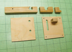
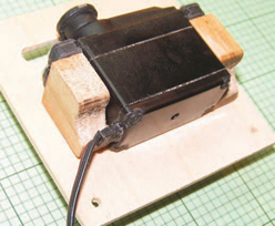
Here are the parts you need: the mounting rails, servo attachment blocks, and hatch covers. The cover to the left has two holes in it forming the ends of the slots. Remove the material between the holes, and sand it smooth.
With the blocks attached to the servo with double-sided tape, I lightly press into the blocks with the drill bit that’s centered in the grommet with the brass tube.
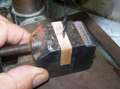
Use a length of brass tube and a drill bit, as shown, to accurately mark the position of the screw holes on the mounting blocks.
For accurate hole alignment, I finish drilling out the holes using my drill press, with the blocks held in a vise.
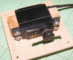
Here is the finished servo installation on the hatch cover. The blocks are glued to the hatch with Z-Poxy so that the servo arm is centered in the slot.
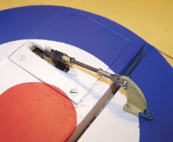
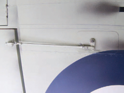
Here the hatch cover is in place in my Sopwith Triplane wing.
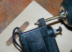
Notice the notch in the block. This allows the servo lead to clear the block without interference.
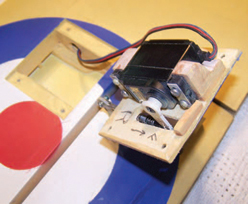
With the hatch cover removed, you can see the attachment rails, which are glued to the wing ribs.
There is another important reason for using two channels, and that is to allow easy setup for differential ailerons. I feel that this applies to trainer, sport, and especially scale models. I’m surprised by how many modelers are not aware of the importance of differential aileron travel, where the travel of the upward-moving aileron is more than the downward-moving aileron. The downward aileron will cause excess drag on the wrong wing (outside the turn), causing adverse yaw. Starting with 50% down to full up will automatically allow for yaw in the proper direction, making scalelike, coordinated turns. Don’t be afraid to reduce it even more. As little as 30% down is not unreasonable. Coupling some rudder in a turn adds to the realism. If you don’t automatically input rudder in a turn (some pilots do, but most don’t), then let your transmitter apply it. Most late-model transmitters have aileron-to-rudder coupling. Start with about 20%.
An education in differential ailerons came my way a few years ago when my good friends Bob Walker (of Robart fame) and Bill Samson decided to enlarge my scale 72-inch-span Windex 1200C powered glider to 96 inches and add ailerons. I published the 72-inch version in Model Airplane News (plan X0801A) in the August 2001 issue. With no ailerons and powered by a Speed 400, it flew great. Bill finished his and really didn’t like the way it flew; it just wasn’t what he expected. Bob was into some other projects at the time, so gave his framed-up Windex to me to finish. The bottom line is that I finished it and wasn’t very happy with it, either. It was good in pitch, fair in yaw and rudder, and not at all good in roll. I increased the dihedral a little, and that made the rudder control better. Some differential was in place when I installed the offset servo arms and control horns, but this was too little for the long, high-aspect-ratio wing. Because I was using a 4-channel radio and could not electronically increase the differential, I increased the offset in the controls (a lot) to give me 7/16 inch up and 1/8 inch down. This, plus a 25% aileron-to-rudder mix, made the Windex a pleasant model to fly. Control-surface adjusting pays off!
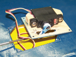
Here is the aileron servo installation in my Windex glider. The servo is smaller than on the Sopwith Triplane, but the technique is the same.
The same arrangement is used in my giant Spitfire fighter. Mounting the servos internally also cleans up the look of your models.
The enlarged Windex has Hitec HS-81 standard microservos on the ailerons. Just under 1/2 inch thick, they just fit into the just over 1/2-inch-high area at the servo location. The servos are screwed to a couple of small maple blocks epoxied to the 1/16-inch-thick plywood cover. If I was doing this again for this application, I would glue the servo to the plywood cover with Pacer Zap Goo because the vibration level is so low. Wrap the servo with a layer of masking tape to make cleanup easier if it is removed. The Zap Goo will hold the servo securely in place. I wouldn’t do this with anything but a small electric or electric-powered glider model.
Most of my giant-scale models have wings that are thick enough to mount the servos with the output shaft vertical, and this makes servo and control-arm access easy. Of course, the arm and pushrod are exposed and might be a static score downgrade in competition!
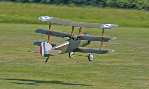
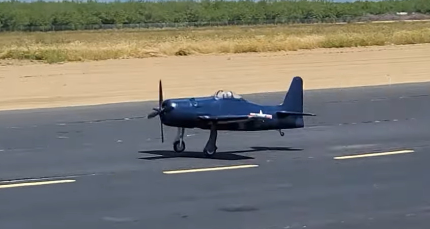
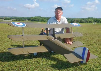
Here is the Sopwith Camel on its first test flight. It performs well and is set up with differential aileron control response to counter adverse yaw.
By Nick Ziroli Sr.