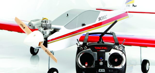
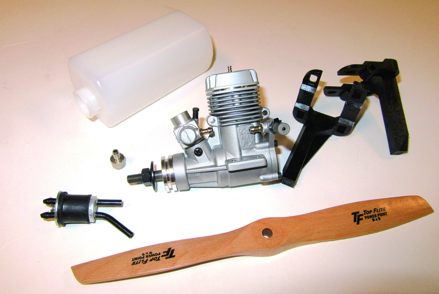
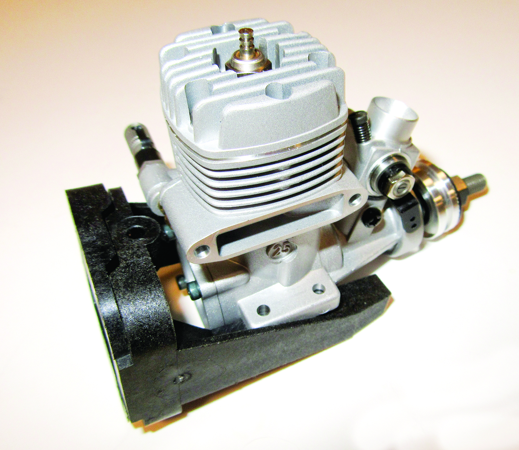
In this article, we’ll highlight the installation of the power system consisting of the O.S. Max .25 two-stroke glow engine, its motor mount, the fuel tank, and the fuel lines. We’ll also install the receiver and the servos in the airplane to control the rudder and elevator, and attach all the control linkages. Let’s get started.
ENGINE INSTALLATION
The Sonic ARF comes with a composite engine mount, and it is molded in two pieces so that its width can be adjusted to accommodate a variety of engines. The two back-plates overlap and can slide back and forth, changing the distance between the two rails. Slip the two halves together and then place the engine in the middle of the rails so that it fits between the two side webs.
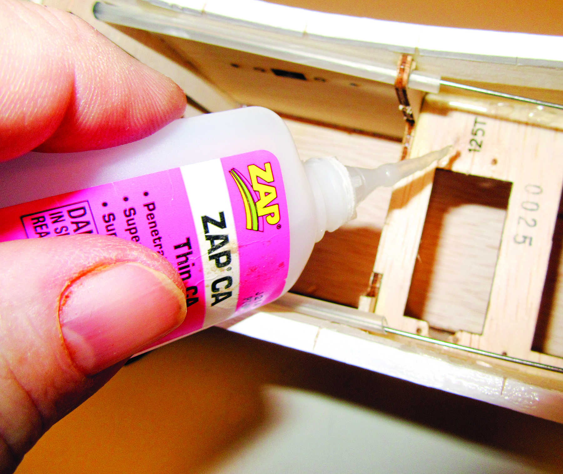
Once you have the engine-mount parts “sized,” remove the engine and place the back of it on a flat surface; press the parts together so that the back is flat with the two pieces flush to each other. Now add a couple of drops of thin Zap CA glue, and spritz with a little Zip Kicker to hold the parts together.
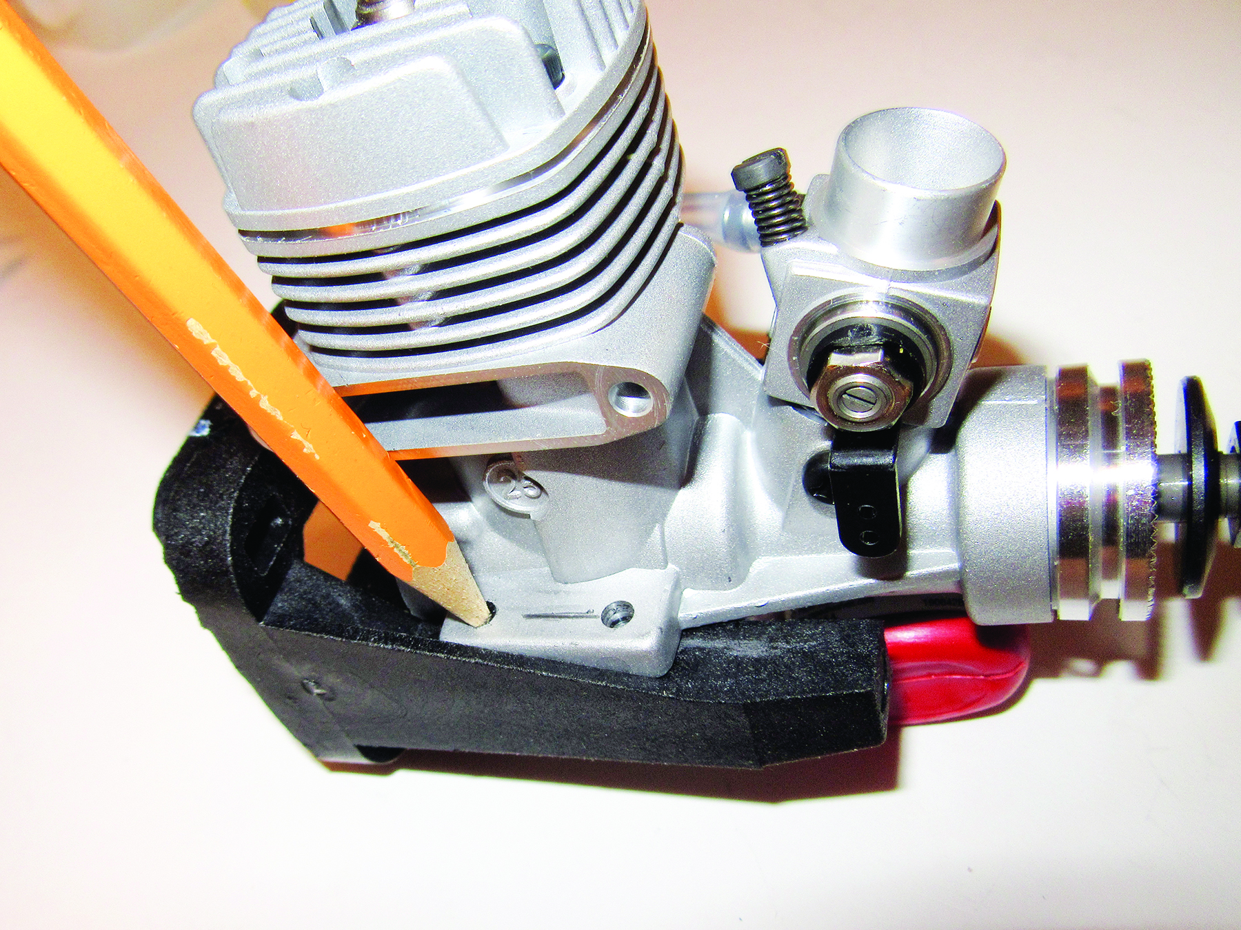
To attach the engine to the engine mount, you first have to drill holes into the rails and use the included screws to secure it into place. Position the engine on the engine mount so that the engine’s attachment tabs are in the middle of the rails, then use a sharp pencil to transfer the locations of the hole onto the tops of the rails.
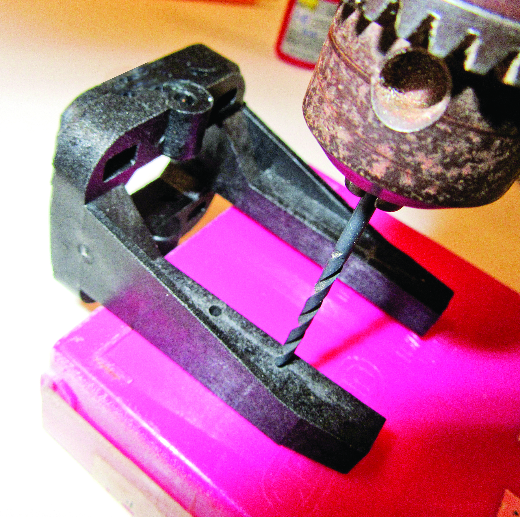
Using a 3/32-inch drill bit, carefully drill the four holes. Make sure you drill the holes so that they are straight vertically and square to the rail tops.
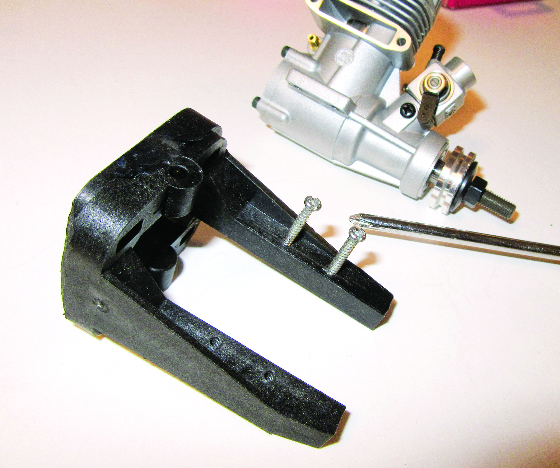
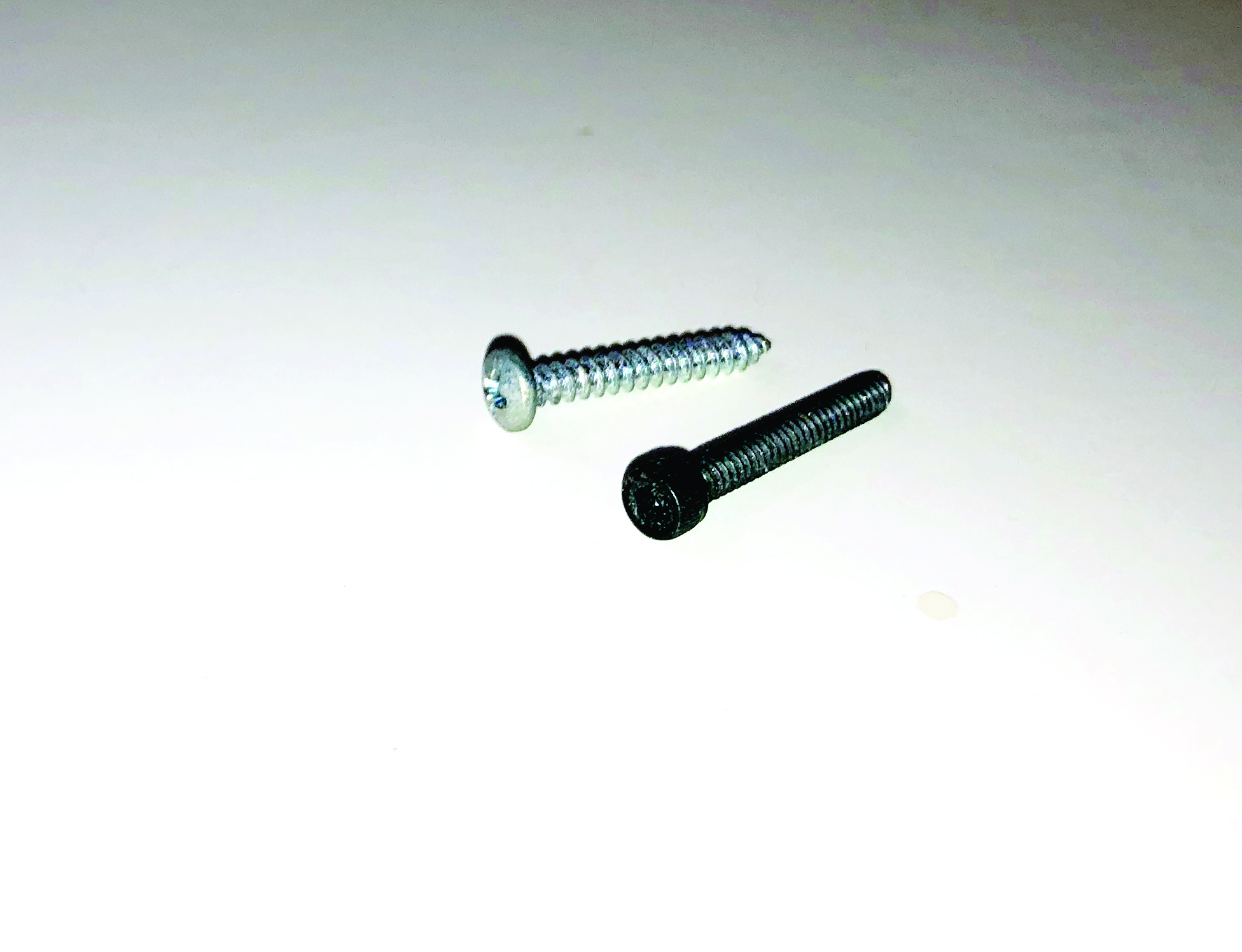
Use the four 2mm x 3/4-inch-long self-tapping screws; insert one at a time, and screw them into place about a quarter inch deep to start the threads. Then remove them.
There are four long 4mm screws that hold the engine mount in place. Insert the screws into the mount and thread them into the blind nuts installed in the firewall. If there are any burrs, it may be difficult to thread the screw into place. Replace the blind nut with a new one. As you thread the screws into place, add a small drop of Zap thread-lock on the end of the screws, and use a crisscross pattern to tighten the screws snugly into place.
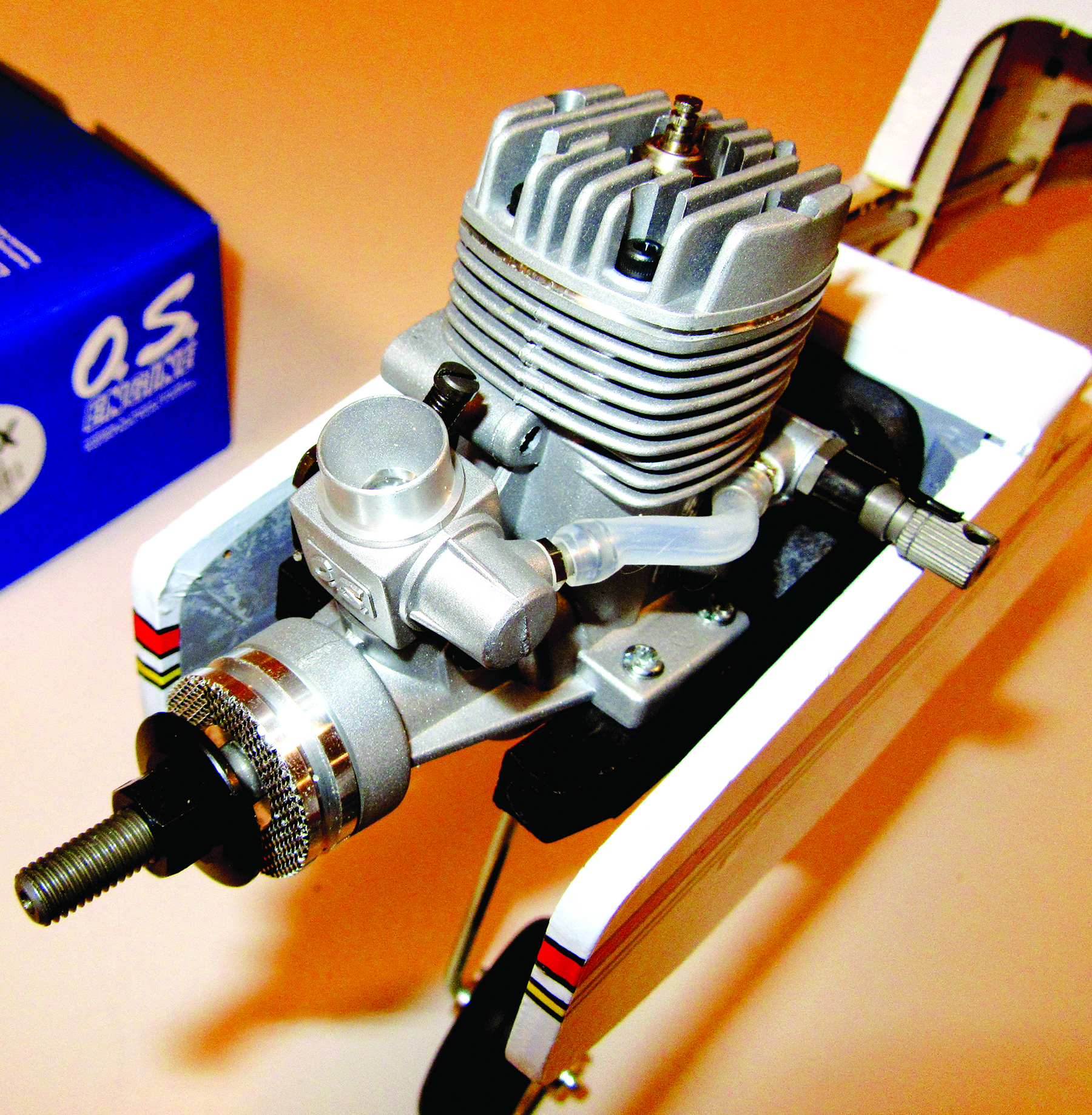
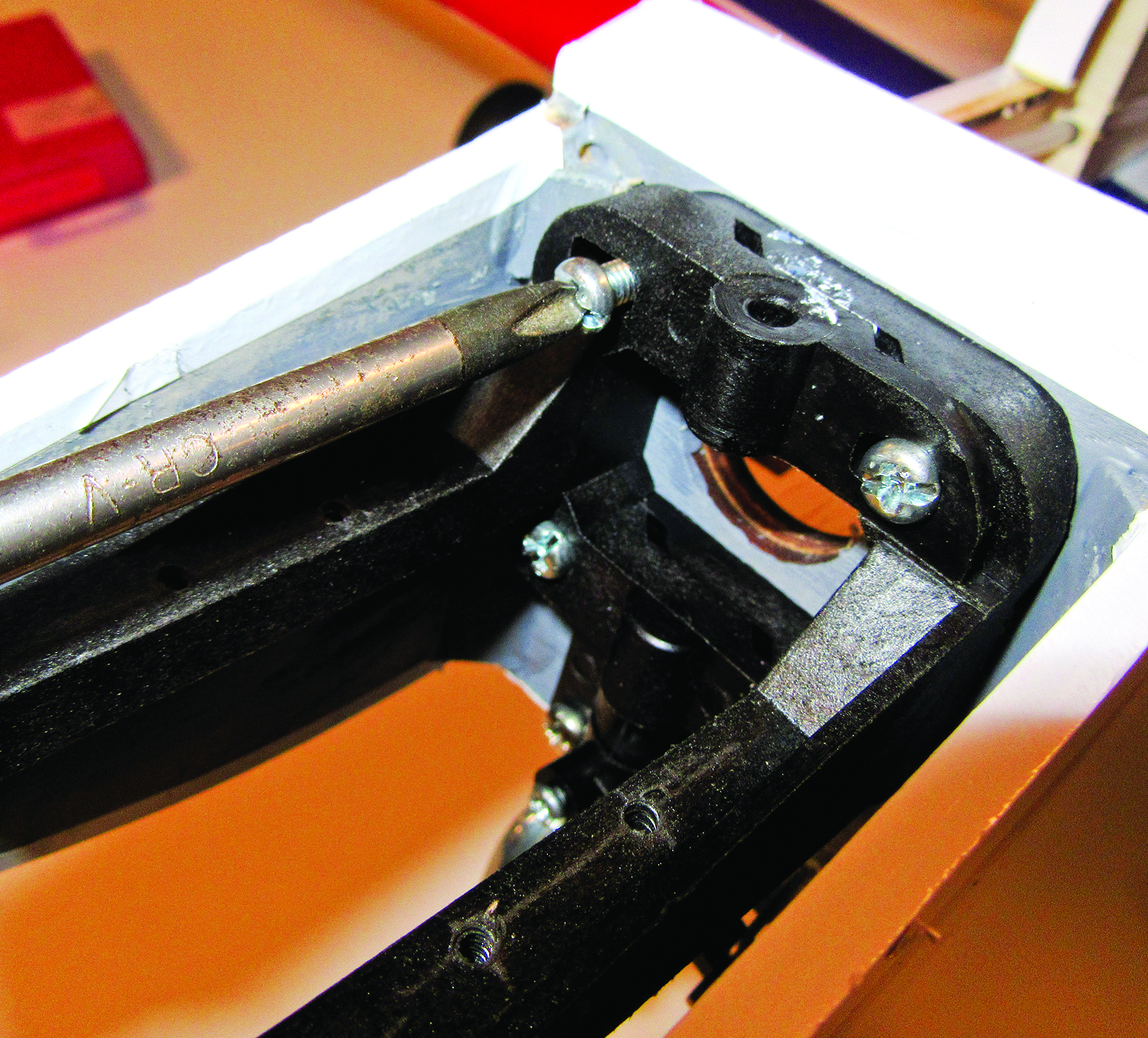
With the engine mount secure, attach the Z-bend end of the throttle pushrod to the engine’s throttle arm, and place the engine on the mount while slipping the pushrod into the guide tube. Reinstall the engine on its mount, and tighten the attachment screws snugly into place. (Note: To prevent damaging the fuel line connecting the carburetor to the needle-valve assembly, remove it before screwing the engine in place.)
TECH TIP 1
Although the included hardware is more than strong enough for the job, you may find it easier to replace the engine attachment screws with 2mm cap-head screws so that you can use a ball-driver Allen wrench to thread them into place. With constant use, the slots in Phillips-head screws will often begin to wear out.
FUEL TANK
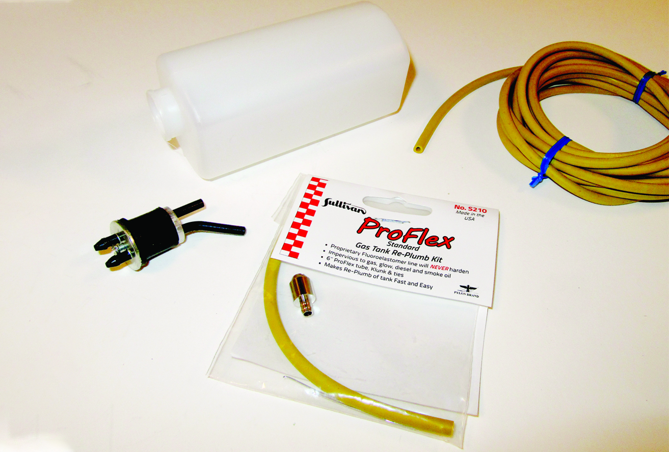
The Sonic ARF comes with a fuel tank and its stopper and outlet tubes, but you have to supply the fuel line. Any glow fuel tubing will work, but I have found that the new ProFlex Universal Fuel Line works extremely well. It doesn’t harden over time and is extremely flexible, which helps prevent it from slipping off of the fuel fittings.
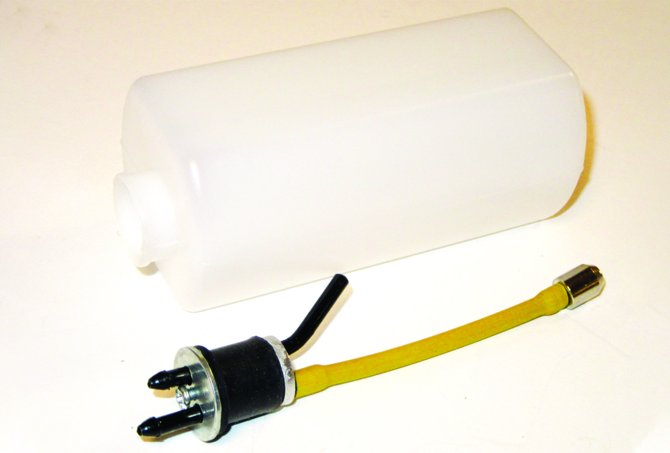
Check the opening of the tank to see if there is any sharp flashing present. This could cut into and damage the rubber stopper. If there is, use a sharp hobby knife to cut it away, producing a slight bevel on the inner edge. Cut a piece of the ProFlex fuel line to length so that, when you slip it onto the outlet tube, it is about half an inch shy of reaching the back of the fuel tank. Slip the metal fuel pickup “clunk” into the end of the pickup line and then slip the stopper into place to check the pickup line’s length. With the stopper pushed all the way in, the clunk should be about 1/4 inch shy of hitting the back of the tank. If it touches the bottom, remove the assembly and shorten the pickup line.
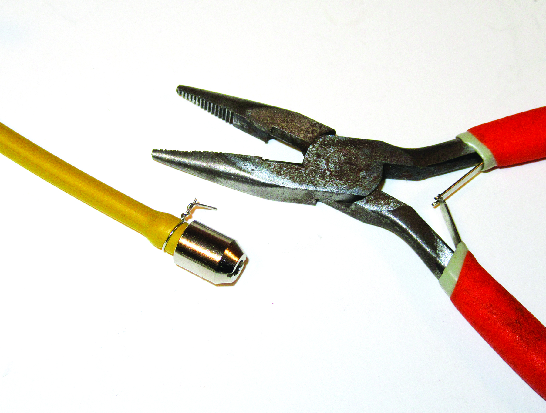
The ProFlex fuel line comes with thin pieces of wire that you wrap around and twist into place around the neck of the clunk. Using long-nose pliers, twist the wire tightly into place so that it clamps around the line, then snip off the end so that about 1/8 inch remains. Since the outlet and bent vent tubes are made out of plastic, do not use the clamping wire at those line attachments. Do not attach any fuel tubing to the inside of the vent tube.
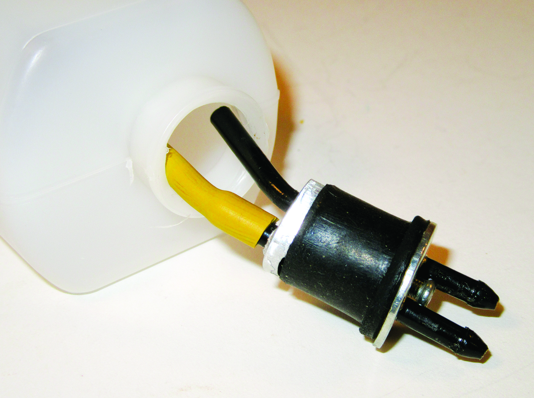
The top of the tank is closest to the stopper and tank neck. Insert the fuel line and stopper unit into the tank, and position it so that the vent tube is at the top of the tank, then tighten the screw until the stopper is tightly secure in the neck of the tank. You shouldn’t be able to twist or turn the stopper.
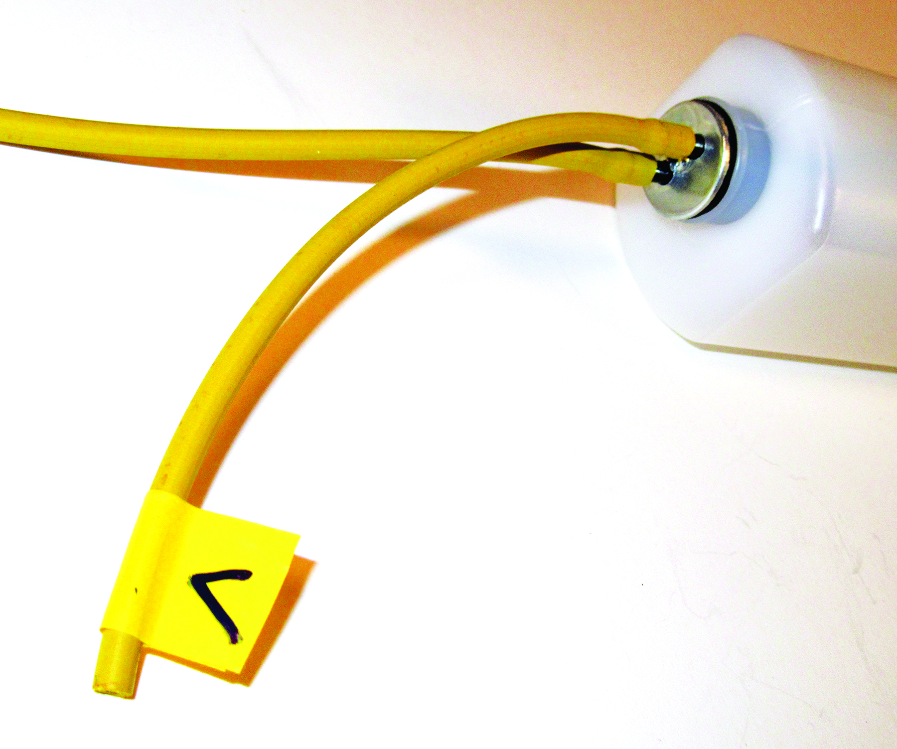
Before installing the tank in the fuselage, cut two lengths of fuel line about 6 to 8 inches long and slip them onto the fuel outlet’s tubes. Add some tape to the vent line, and identify it with a “V” to help prevent attaching the fuel line incorrectly to the engine.
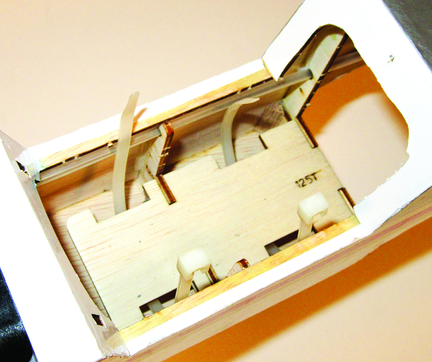
To install the fuel tank in the fuselage, loop two heavy-duty cable tie-wraps under the fuel-tank tray through the side notches so that the ends extend out of the fuel-tank compartment.
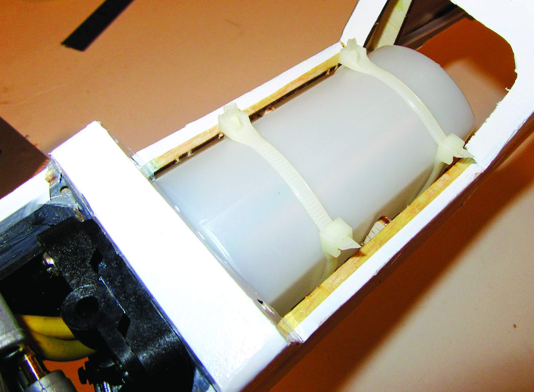
Slip the tank into the fuselage, and push it back so that the front can clear the front of the hatch opening. Insert the two fuel lines through the opening in the firewall, and pull them out as you slide the fuel tank forward. The neck and stopper of the tank fits into the firewall opening. Add a second tie-wrap to each of the other two, and tighten them so that they hold the tank firmly into place.
Snip the ends off of the tie-wraps, then trim away some material from the bottom of the hatch cover so that it clears the tie-wraps. The hatch cover is held in place with a spring-loaded latch.
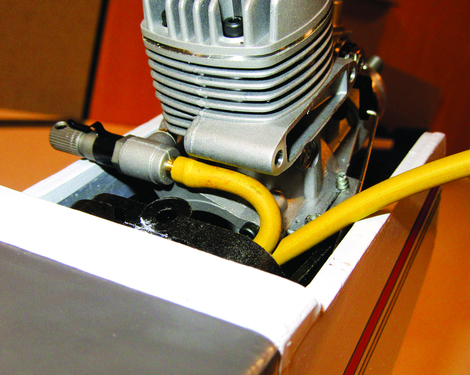
Allow about 2 inches of excess length and cut the fuel-supply line to length, and slip it onto the fuel fitting on the back of the engine.
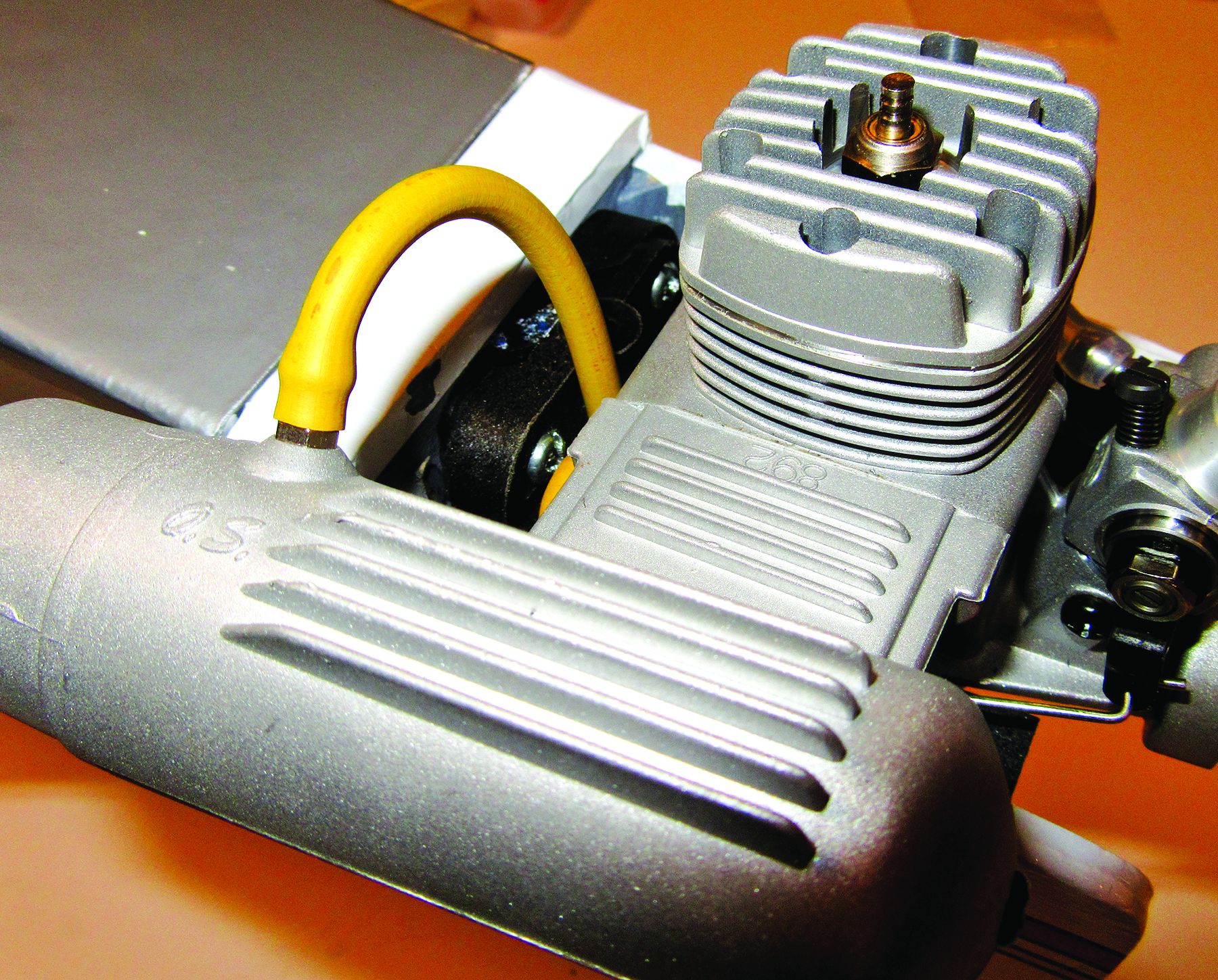
Install the muffler on the engine, securing it with two black machine screws and lock washers, and connect the vent line to the muffler’s pressure fitting, also allowing a couple of inches extra length.
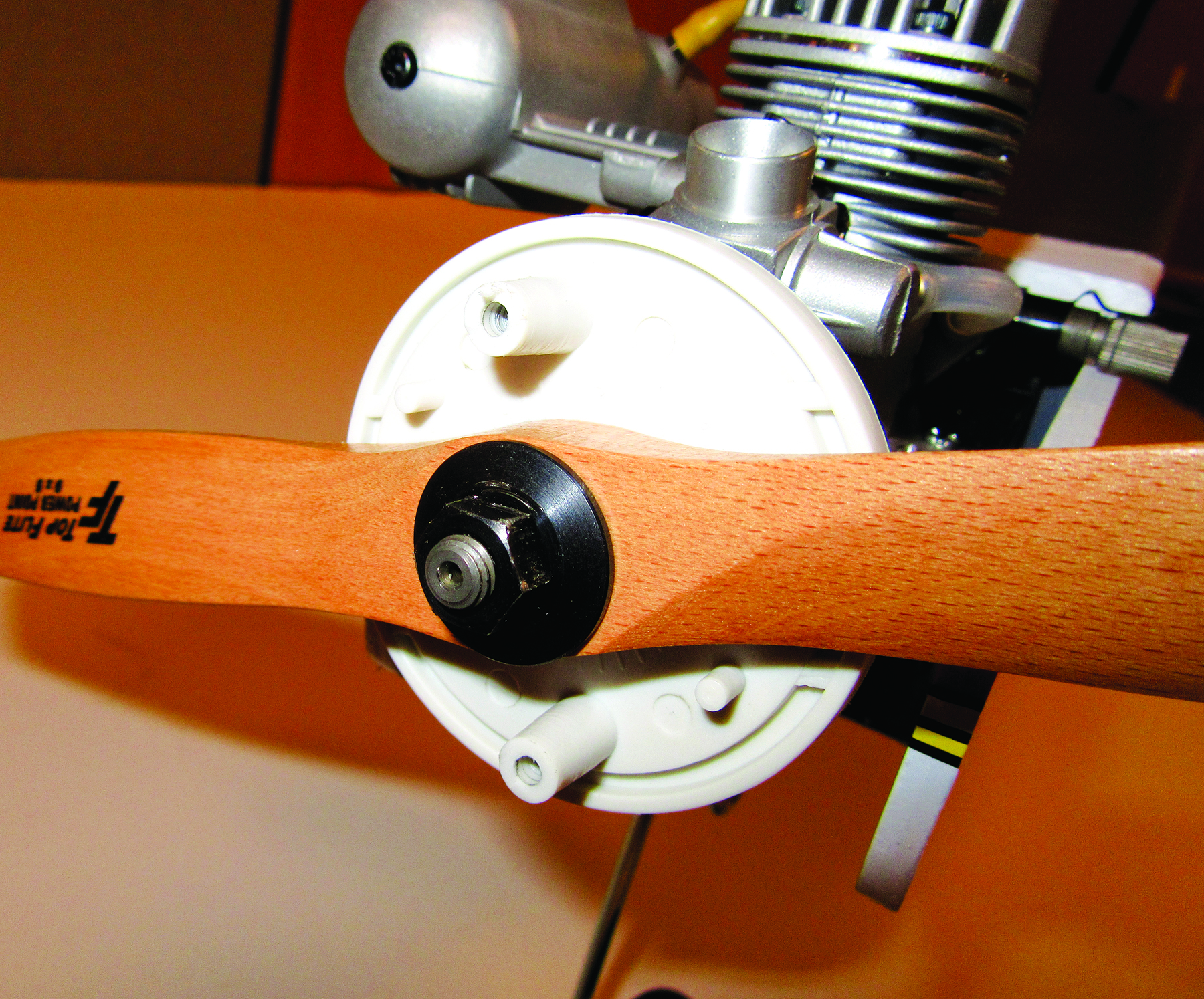
To complete the power-system installation, all you have to do is install the included spinner and a Top Flite 9 x 5 Power Point propeller. The hole in the spinner backplate should be enlarged slightly so that it slips over the engine’s prop shaft with little to no play. Place the backplate against the engine’s thrust washer and the slip the propeller in place, followed by the prop washer and prop nut. Tighten the prop nut down snugly, then give it another quarter turn to really tighten it into place.
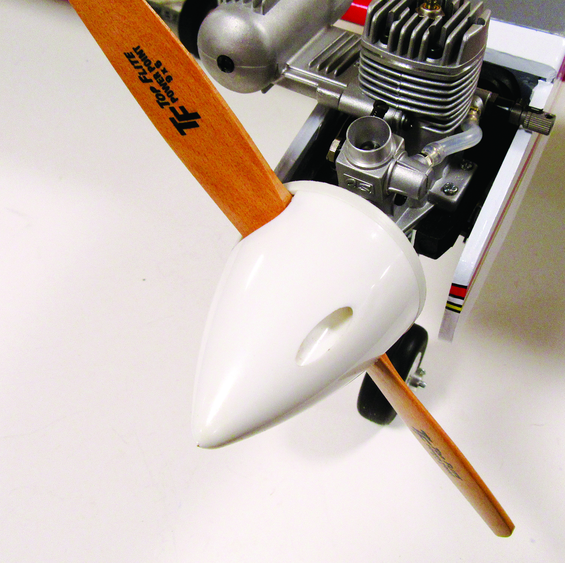
There are two molded-in prop guides in the channel around the backplate, which the lip of the spinner front fits into. The propeller should be positioned in between these guides so that the blades fit in the spinner cutouts. Position the front of the spinner in place and then screw it to the backplate with the two 2mm x 1/2-inch screws.
RADIO INSTALLATION
The next thing to tackle is the installation of the control linkages for the elevator, rudder, and throttle, along with their servos and the rest of the radio gear. Again, as we mentioned in the last issue, all the grommets and brass inserts have to be installed correctly in the servo-mounting tabs. Plug the servos into the receiver, and power up the transmitter and receiver to center the servo output shafts. You should also jot down which servos connect to which receiver ports. With the Tactic TTX650, the aileron lead mates with port 1, the elevator plugs into port 2, the throttle goes into port 3, and port 4 is for the rudder. Once this is done, we will install the servo arms after we work out the control linkages and attachment points.
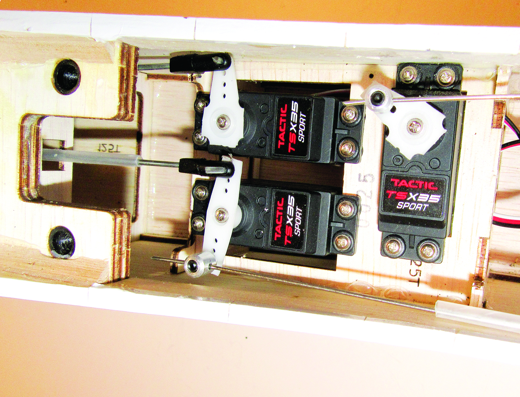
SERVO INSTALLATION
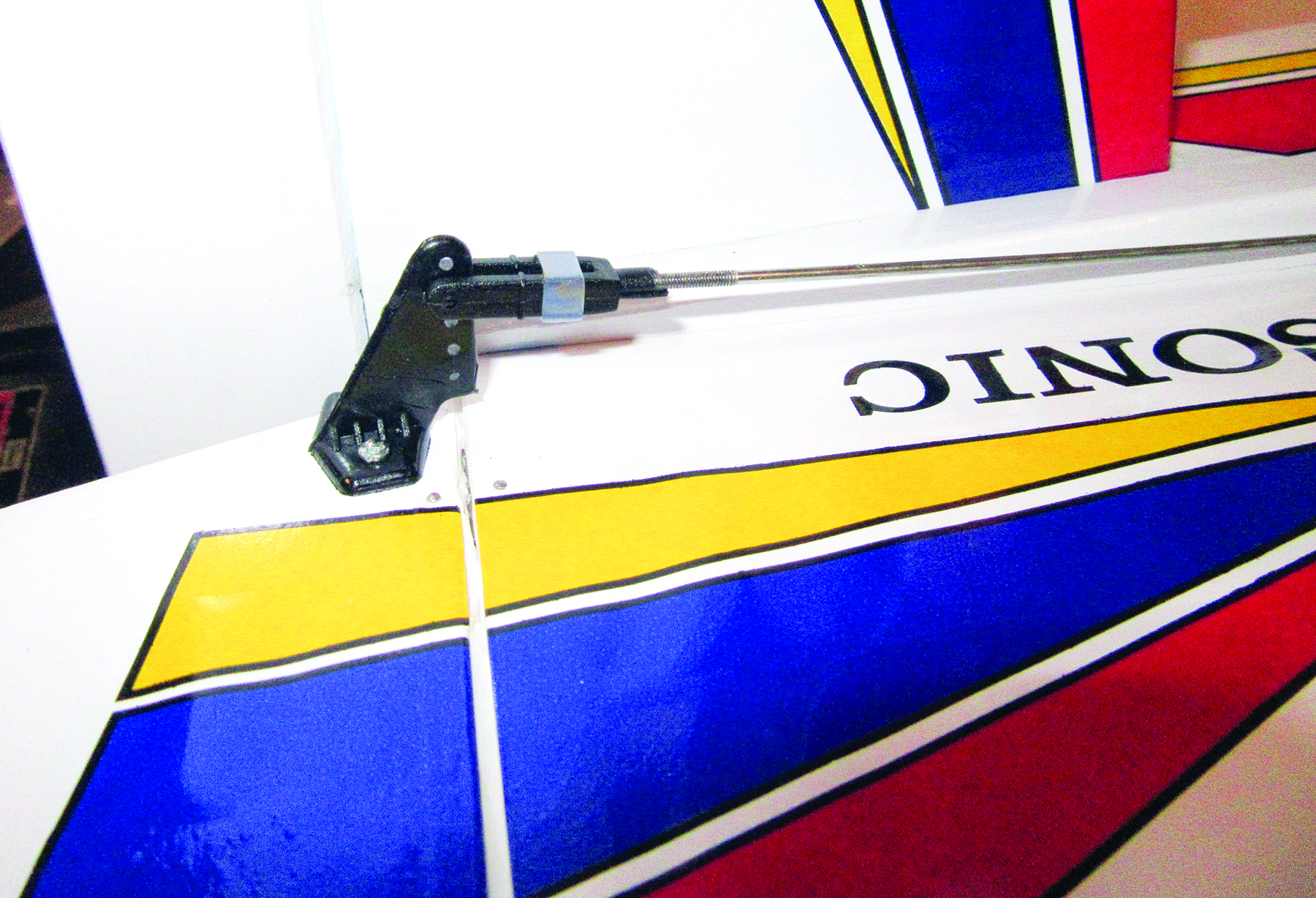
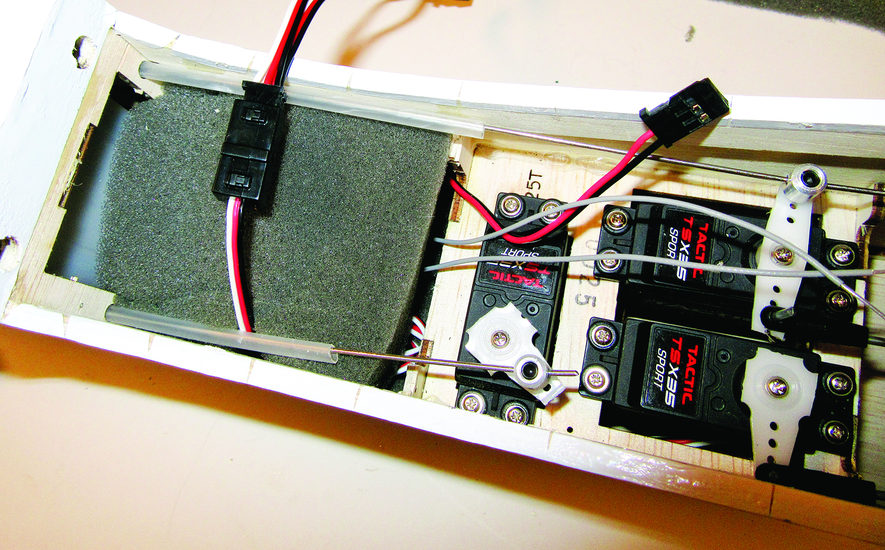
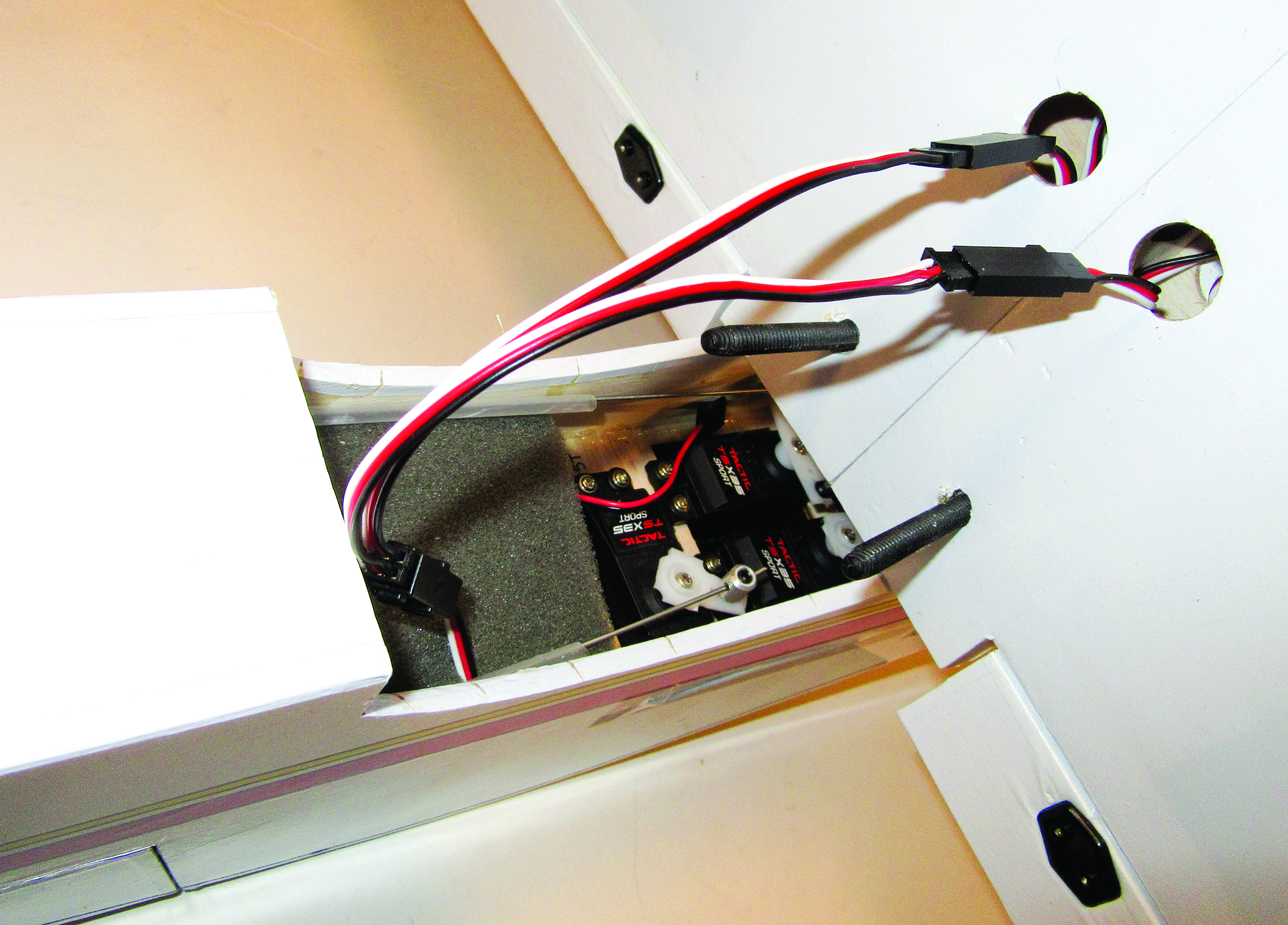
Before installing the servos it is a good time to install the rudder and elevator control horns and the wire pushrods. You will have to cut away the covering from the guide tube exits so you can slide the pushrods into place. Screw the clevises to the threaded ends of the wire pushrods and you are ready to go. Inside the radio compartment there is a servo tray glued into place. Using the instruction booklet as a guide, position the servos as shown. I find that adding one servo at a time and then adding its control linkage is the easiest way to work in the confines of the narrow radio compartment. You remove the wing and then work through the open wing saddle.
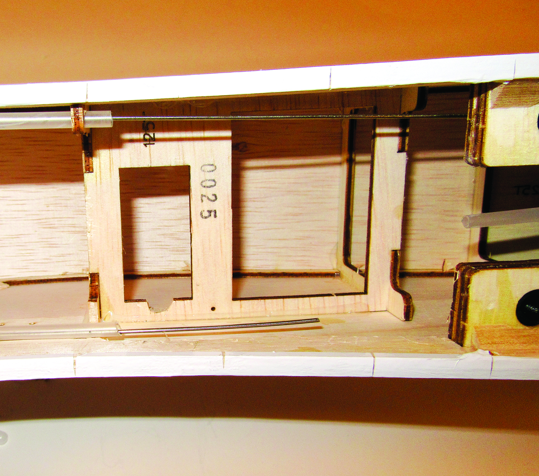
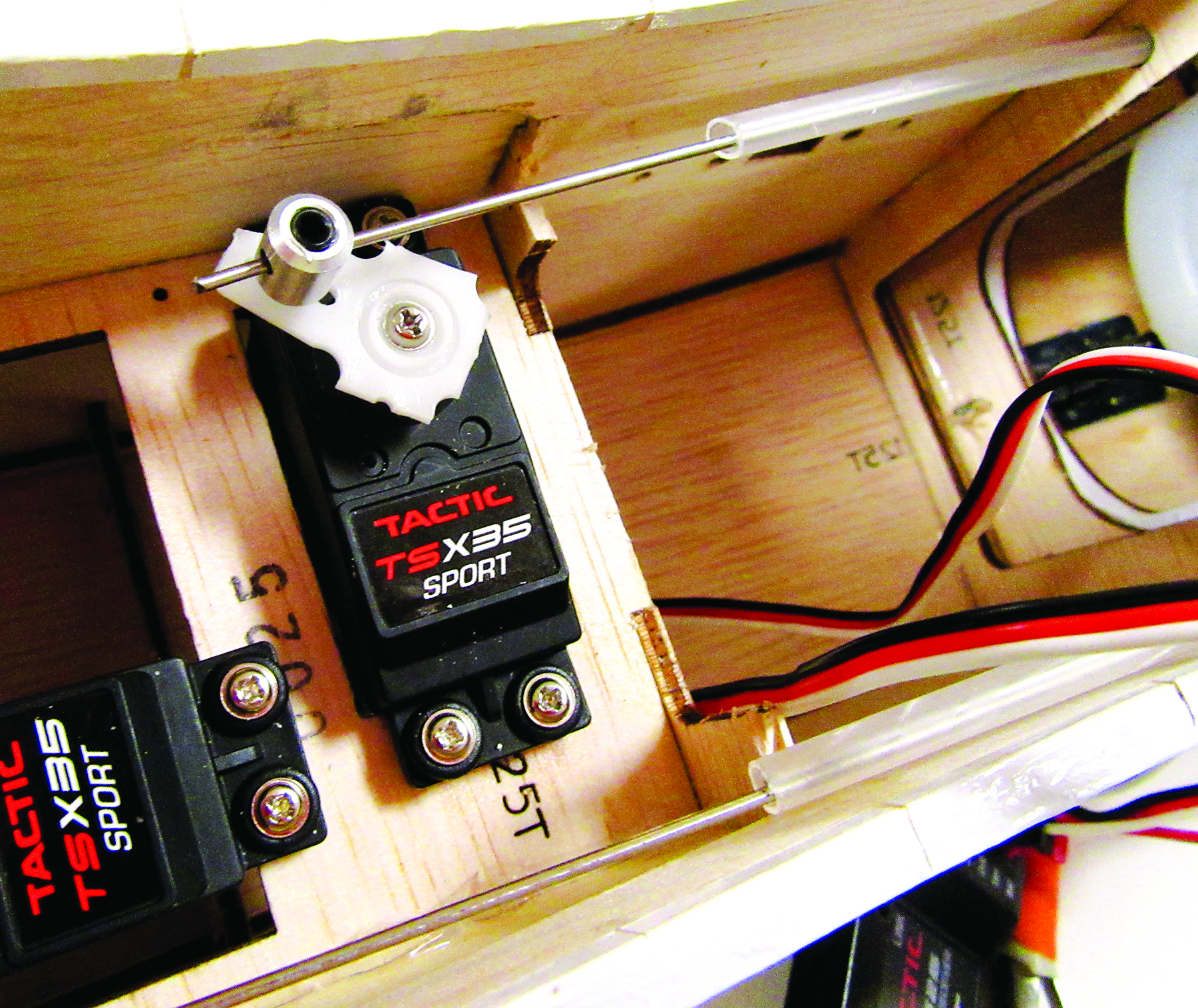
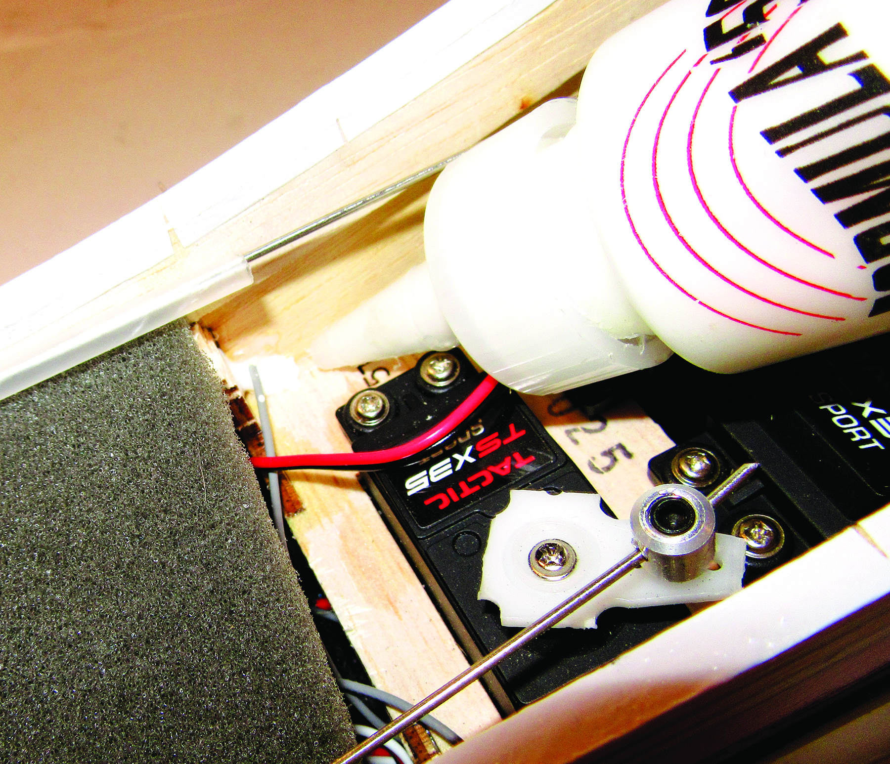
I started with the sideways-mounted throttle servo as it is a tight fit and the tray needs a little trimming to clear the servo leads. Using a sharp hobby knife, notch the servo opening as shown; this allows the wires to be routed under the tray without pinching.
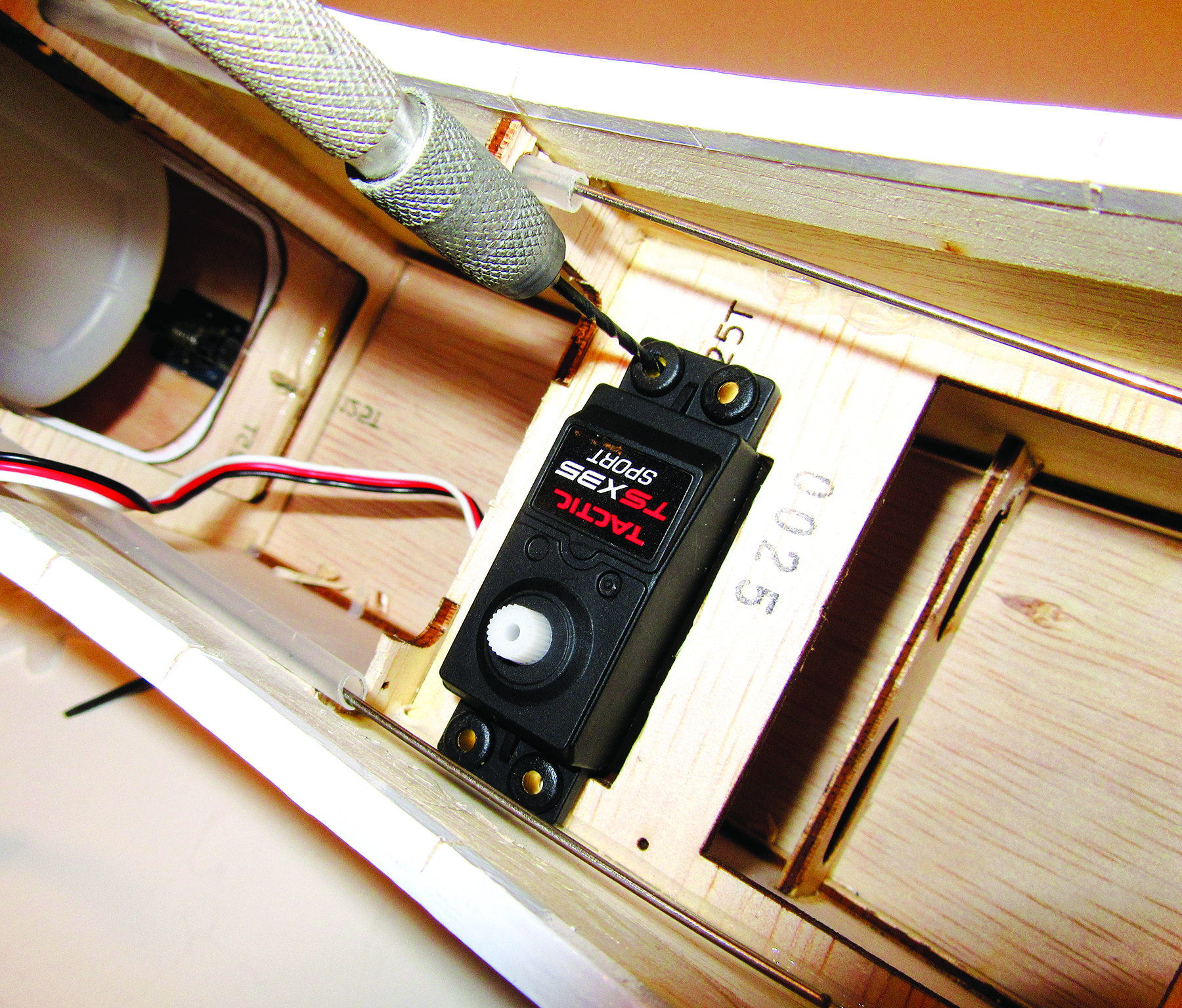
While holding the servo in place, use a 1/16-inch drill bit and drill through the servo grommets into the tray; screw the servo into place.
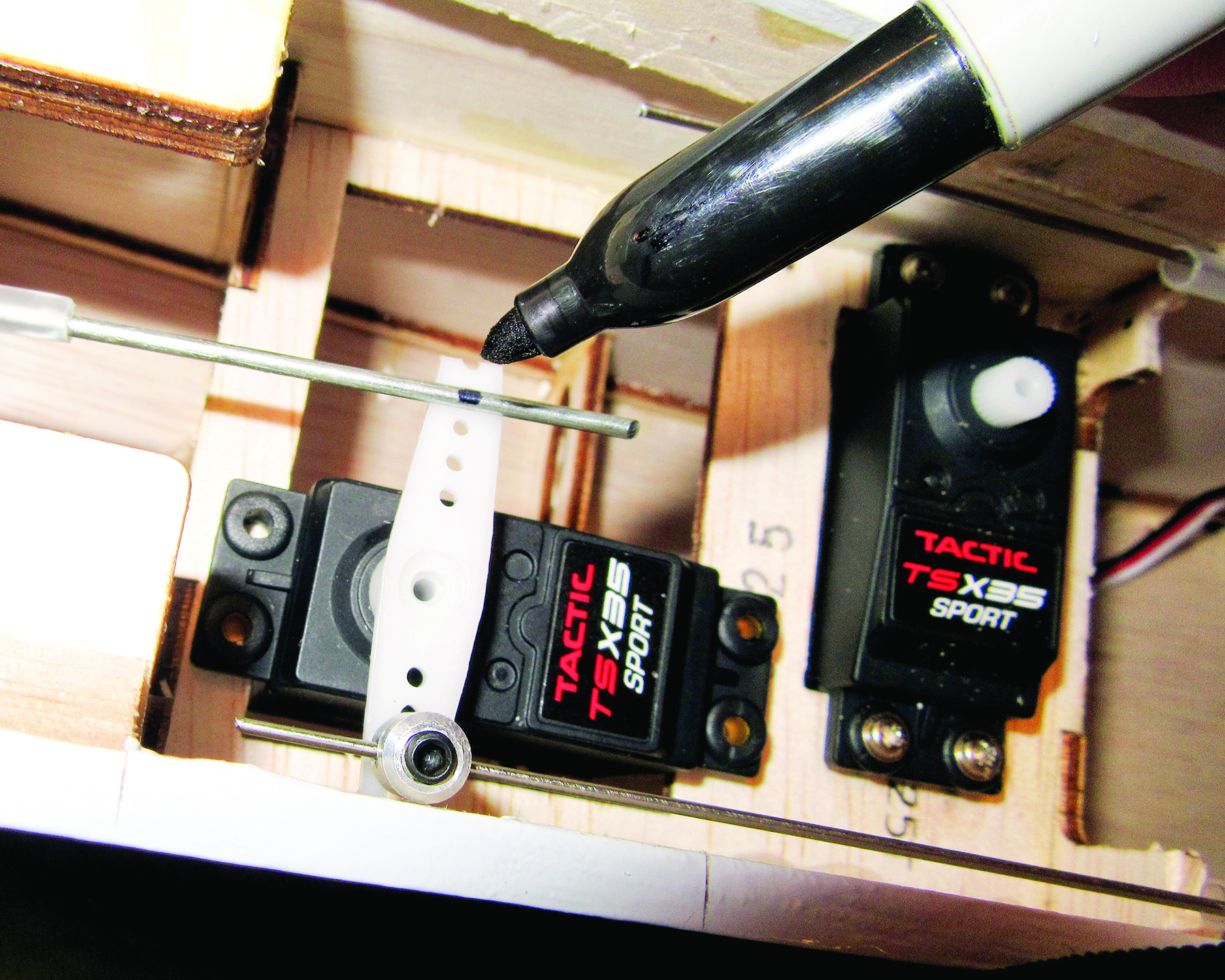
Center the rudder, and mark the pushrod for the servo-arm hole location. Bend the pushrod 90 degrees at this mark, then attach it to the servo arm with a pushrod keeper.
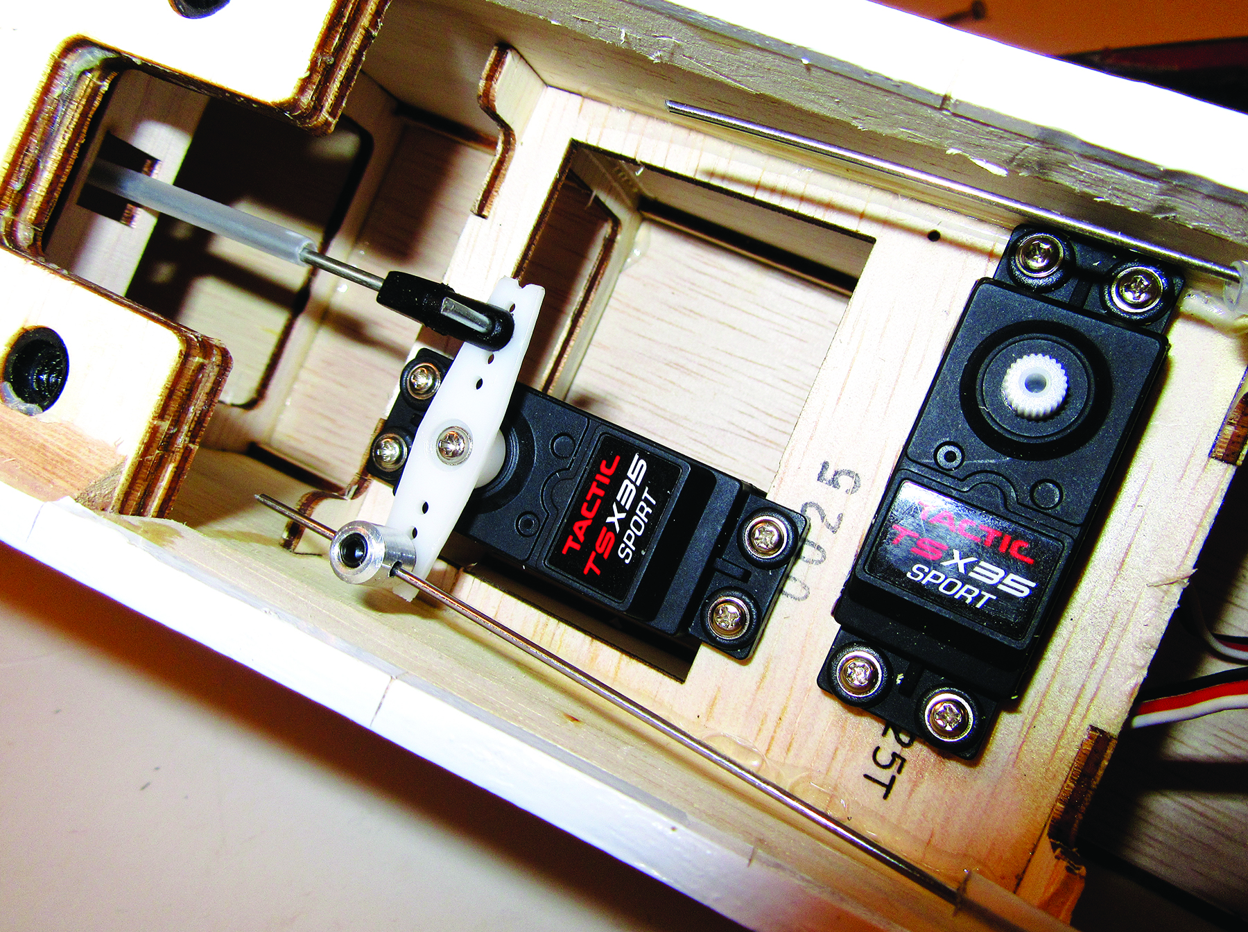
Next, install the rudder servo. You need to use the dual servo arm as the servo will control both the rudder and the nosewheel steering. Position the rudder servo so that the holes in the servo arm align with the wire pushrod and the steering linkage for the nosewheel. While holding the servo in place, drill the holes and screw it into place. For both the throttle and the nosewheel steering linkage, threaded linkage connectors have to be used. These have threaded studs and locknuts used to attach them to the servo arms.
You will have to enlarge the holes in the arms using a 1/16-inch drill bit. Insert the stud in the arm, and with one locknut above and below the arm, use two long-nose pliers to tighten the connector into place. There are holes in the sides of the connectors that accept the control linkages, and on the top is a setscrew to secure the linkage into place. Center the servo, then adjust the nosewheel so that it is centered pointing straight ahead; tighten the setscrew.
TECH TIP 2
With ARF models like the Sonic, the servo trays are often made out of softer wood, such as laminated balsa or light plywood. After you drill the servo-mounting screw holes, add a drop of thin Zap CA to each hole. This will soak into the wood and harden it where the holes are drilled, giving the screws a stronger “bite,” which helps prevent the screws from stripping out the holes.
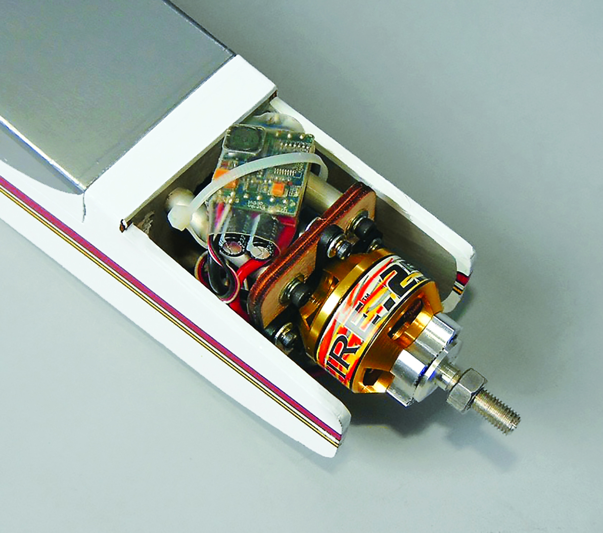
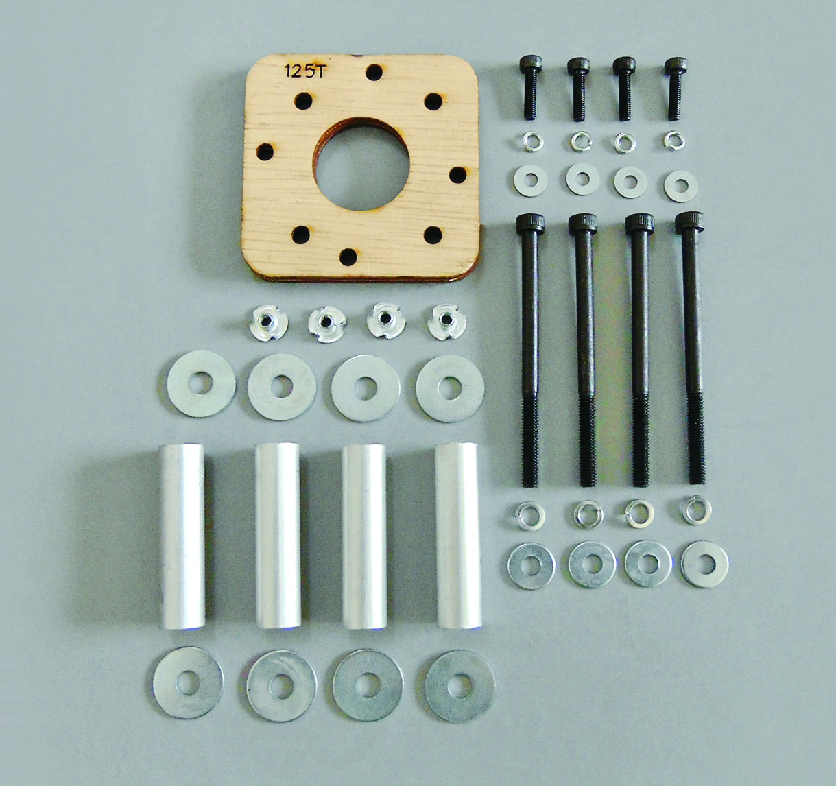
ELECTRIC POWER
As the Sonic is designed to use either a glow engine or an electric power system, here are a couple of photos to show the e-power setup. The model also comes as part of the hardware package, with all the necessary parts to install an electric motor. These include all the aluminum standoffs and screws needed to attach the electric motor. For the Sonic, an ElectriFly RimFire .25 is recommended along with an ElectriFly 30A to 40A speed control. The wiring is easy as it is a plug-and-play and the speed controller is attached to the standoffs behind the model, out in the breeze for abundant cooling. Since the fuel tank is not needed, the tank tray is where the 3S 2000–3000mAh LiPo flight pack is installed. To select the proper e-power propeller, check the instructions that come with the motor.
THROTTLE LINKAGE
The throttle servo is different from the rest of the servos as it does not rest in the centered position. To install the throttle linkage properly, you first have to use the transmitter and bring both the throttle stick and the throttle trim down to the idle positions. Typically, the throttle arm on the carburetor has a relatively short travel, so you should use a short servo arm, or you can use the second-to-last inner hole in the arm as the attachment point and cut the servo arm so that it clears the side of the fuselage.
Install the linkage connector and then insert the throttle pushrod. Pull the linkage back so that the carburetor closes fully, and tighten the setscrew at the top of the connector. Move the throttle stick all the way forward and check the movement of the carburetor’s throttle opening. It should be fully open with the stick all the way forward; if it isn’t or if the pushrod moves too far and bows slightly at the full-power position, you can adjust the servo travel later so that there is no binding in the linkage.
The elevator servo and linkage is the next one to do, and it is done in the same way as the rudder servo. Position the servo, using the arm as a guide so that it does not touch the fuselage side, and drill the holes and screw it into place. Center the elevator position, align the pushrod with the servo-arm attachment hole, and mark the pushrod wire. Bend 90 degrees at the mark, and attach the pushrod to the arm using the keeper to secure the linkage. At this point, you can turn on the radio system and check the movement of the servos and the control surfaces and linkages. There should be no binding throughout the servo arms’ movement.
RECEIVER AND BATTERY PACK
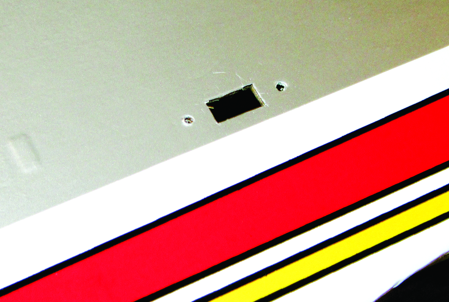
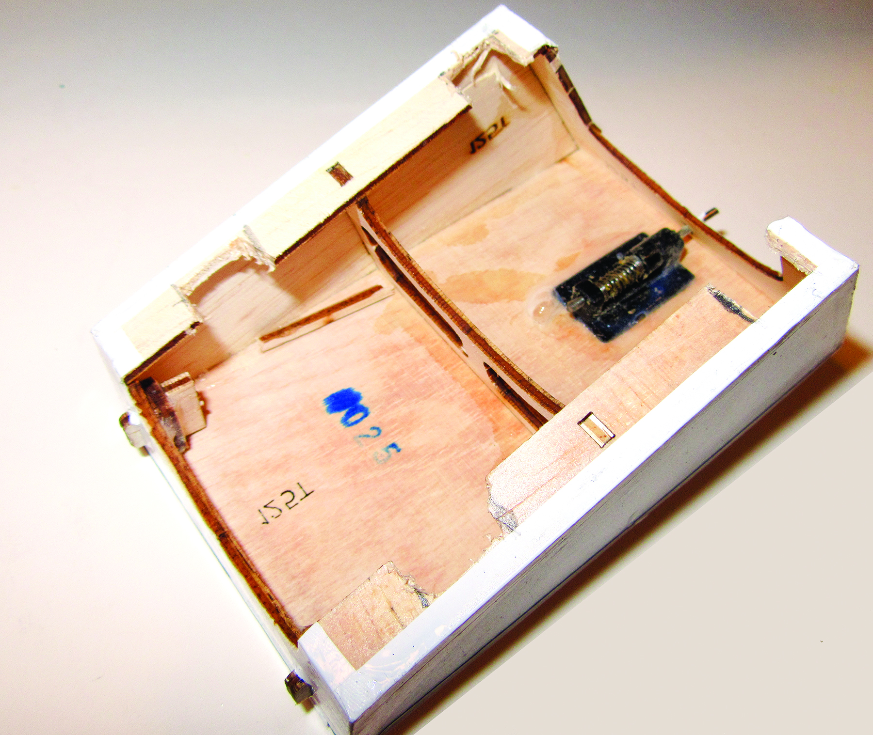
There is a square opening in the side of the fuselage, and this is where the radio power switch is installed. There are also two holes at the sides of the opening, and you can pop them open with a small screwdriver.
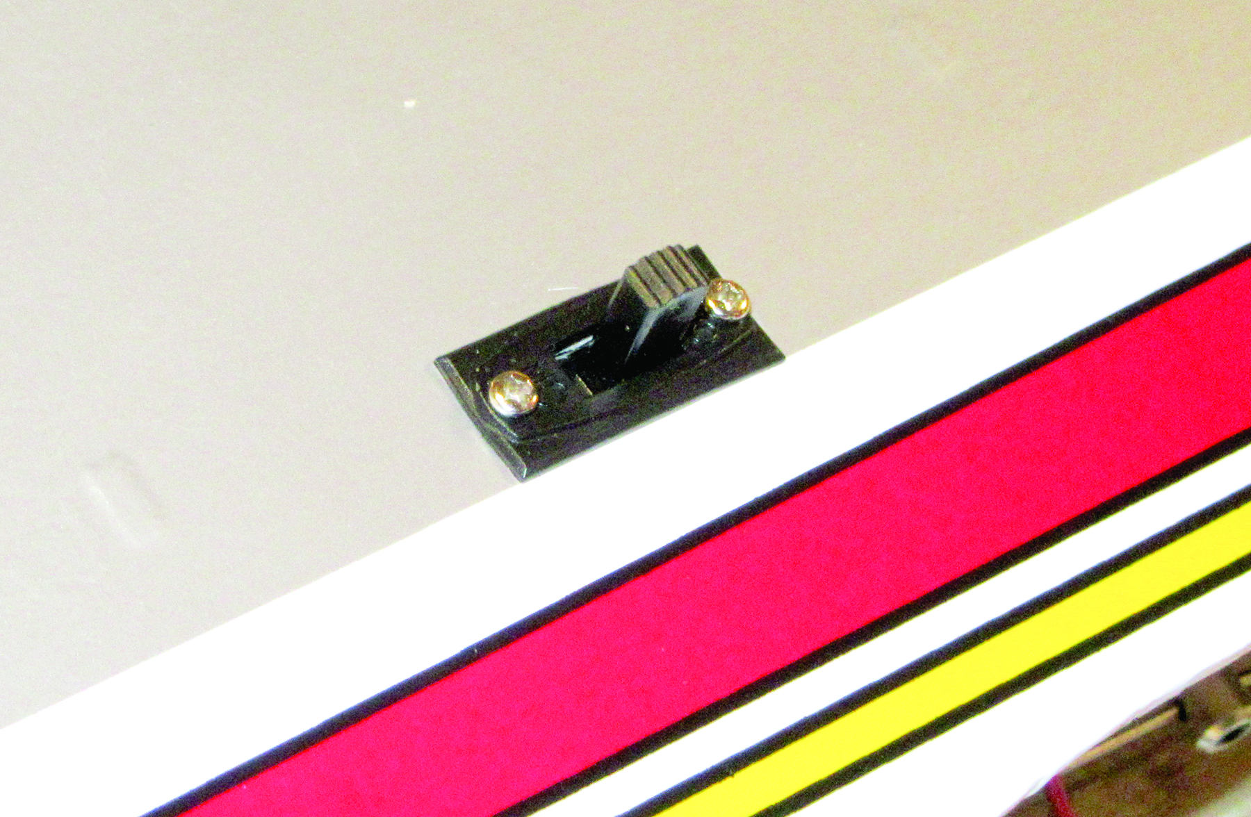
Remove the switch cover, and position it with the “off” position facing the rear of the airplane. Insert the switch harness from inside, and screw the switch and switch cover together.
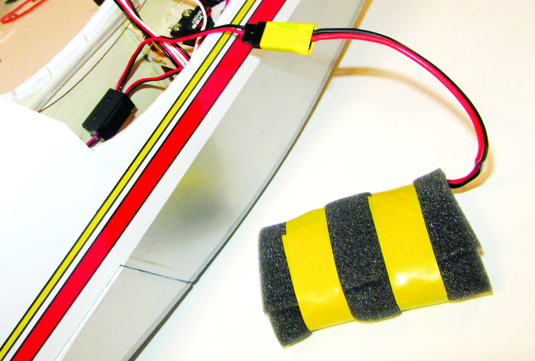
For a bit of safety during flight, use a piece of electrical tape and secure the battery pack’s lead to the switch harness female connector. This will prevent vibration from causing the wires to come apart. Wrap the battery pack with 1/8-inch-thick packing foam, and secure it in place with two lengths of tape. Place the pack in the bottom of the radio compartment in front of the servo tray. Check all the servo leads as well as the switch-harness connector, making sure they are properly and completely plugged into their receiver ports.
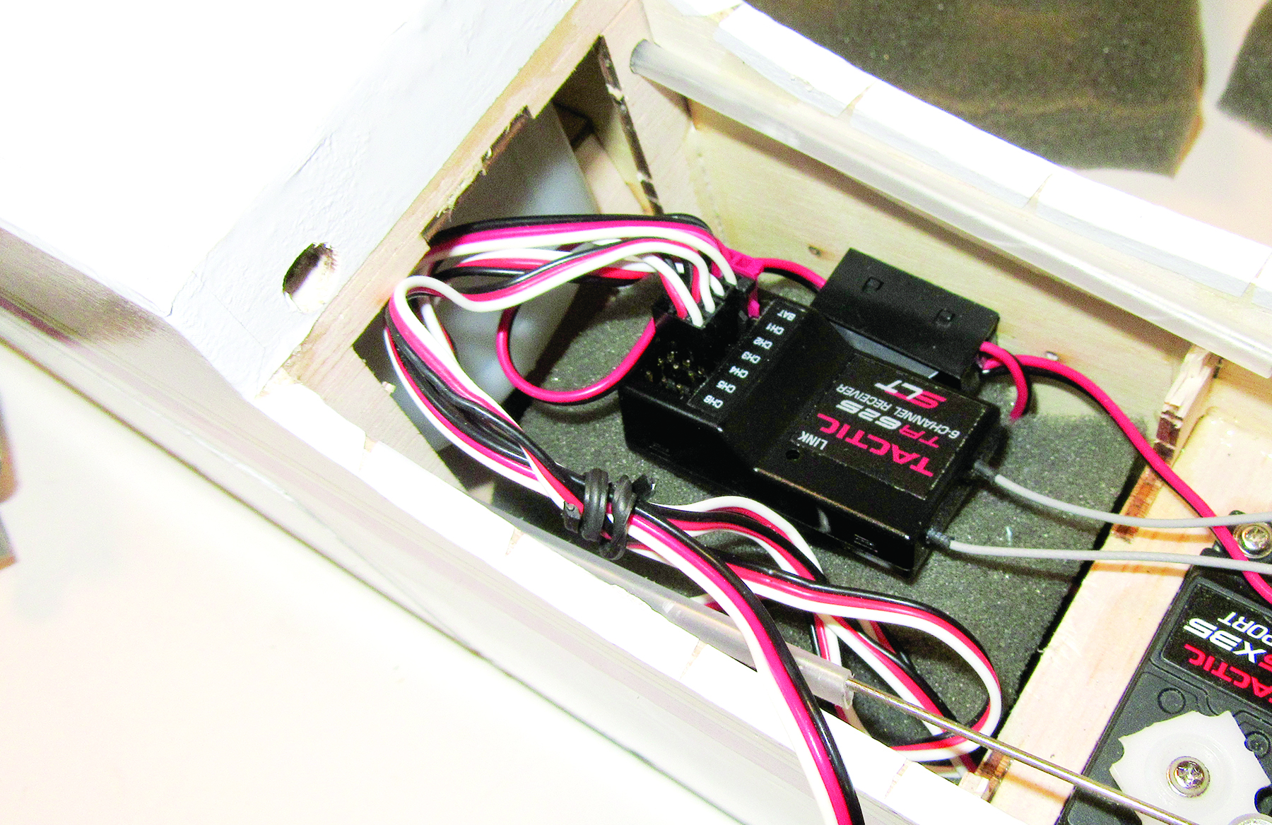
Place a 1-inch-thick piece of packing foam over the battery pack. This piece should be oversize by about half an inch so that it stays in place when inserted into the radio compartment. Position the receiver in the center of the foam. Using one of the wire wraps that comes with the new servos, gather and bind the servo leads together. This keeps the radio installation neat and helps prevent any of the servo leads from getting chafed by the servo linkages.
Place another piece of 1-inch foam over the receiver, making sure that the dual antennae, the charging plug, and the aileron Y-harness are all accessible.
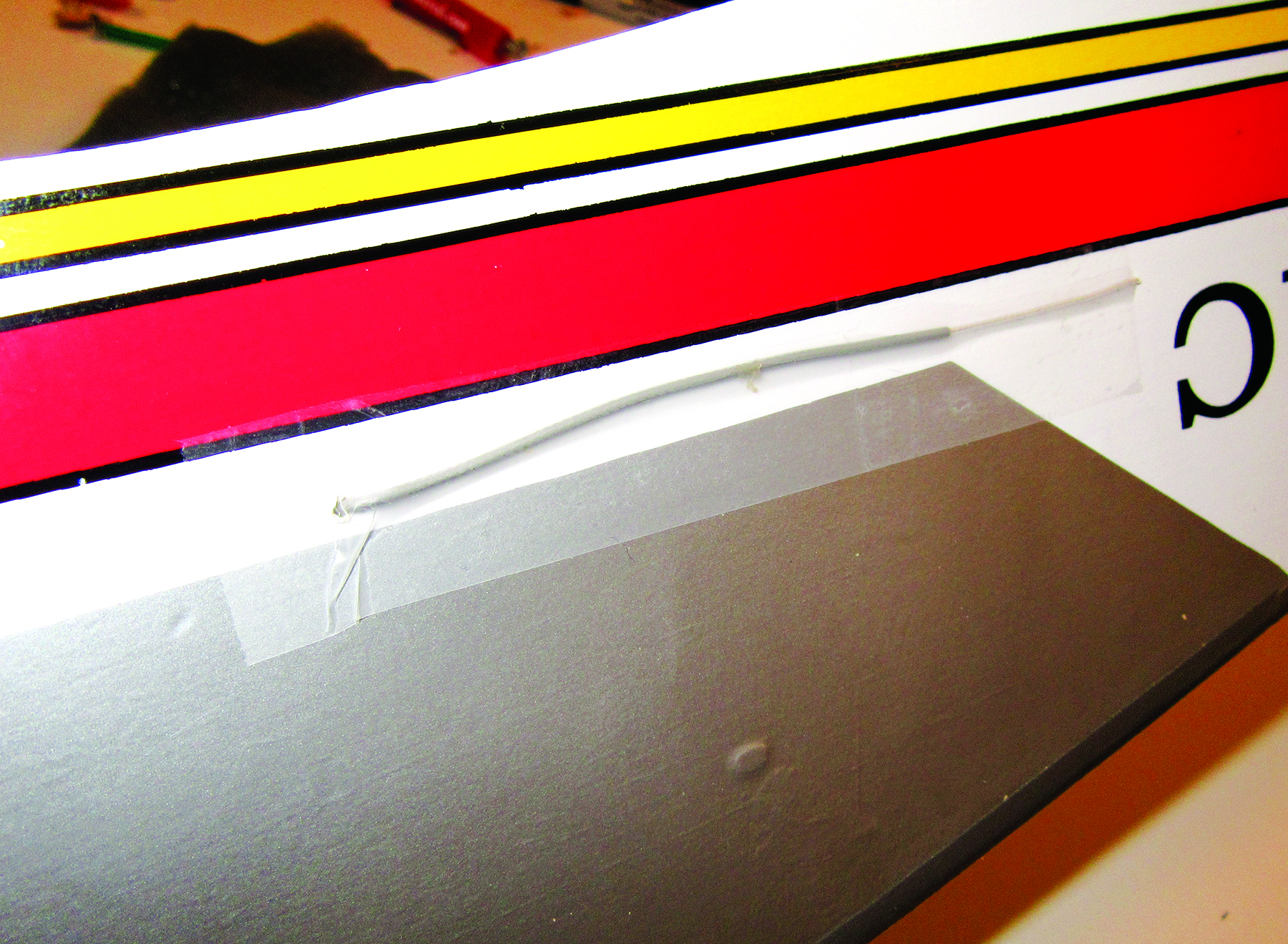
There are two antenna leads with the Tactic receiver, and they have to be installed so that the two outer ends are placed 90 degrees to each other. The easiest way to do this is to drill small holes in the sides of the fuselage and guide them through to the outside. Pull one all the way out, and tape it to the outside of the fuselage so that it points to the tail. Be sure not to have any tension on the antenna where it is connected to the receiver.
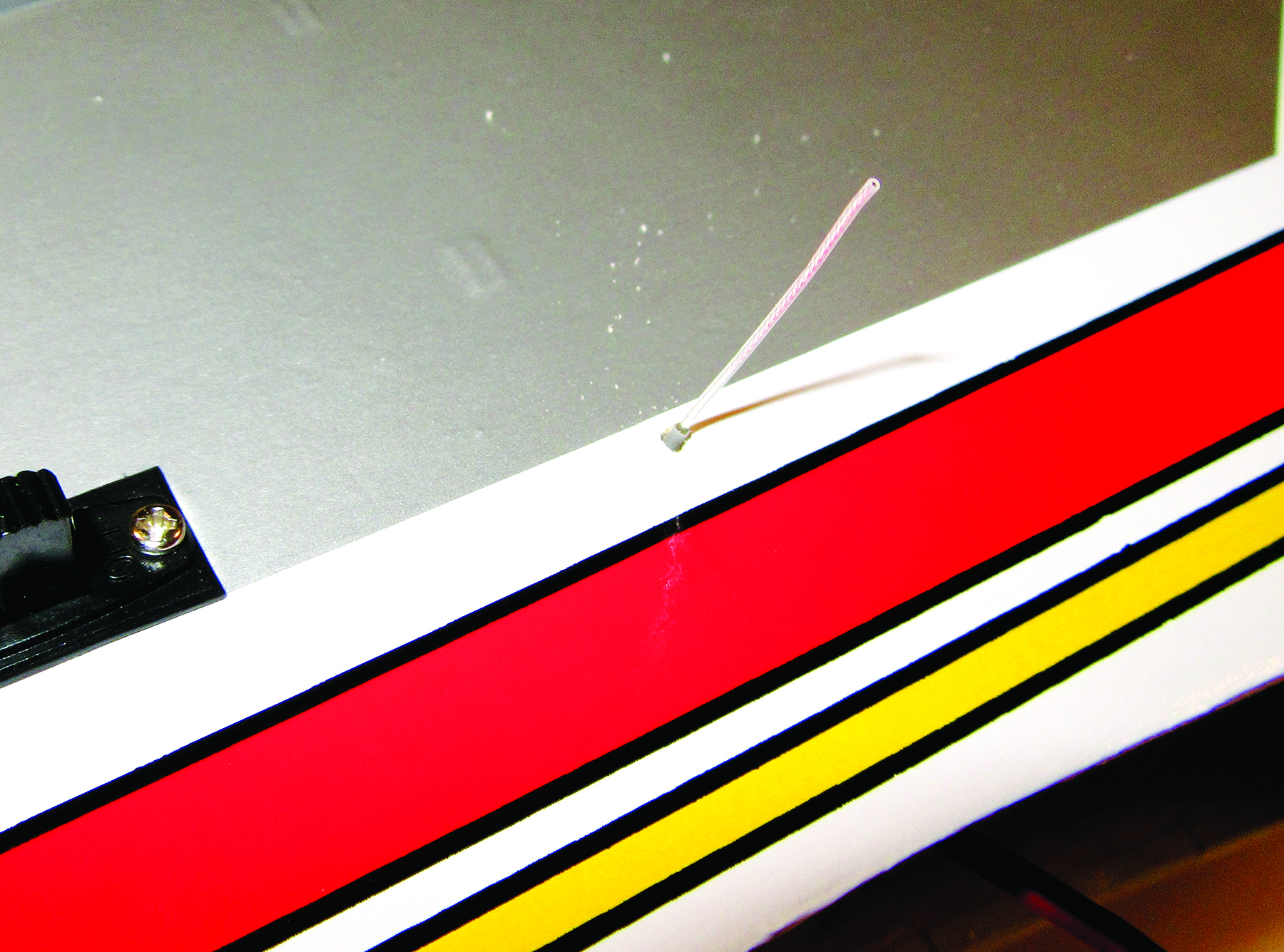
For the other antenna lead, insert it in the hole on the other side of the fuselage so that only the very end of the antenna is exposed and it points 90 degrees from the fuselage side.
Use a few dabs of Zap Canopy Glue to secure the antenna leads where they go through the holes, and let dry. This glue remains flexible when cured and holds the antenna leads in place, but it is easy to remove later on.
FINAL ASSEMBLY
All that’s left to do is to connect the aileron leads coming out of the wing to the Y-harness and then attach the wing to the fuselage. Make sure you push the wire leads back into the holes in the top of the wing, and be sure not to pinch the wire leads between the wing and the wing-saddle sides. When everything is aligned, tighten the two wing attachment bolts. You are now done building your Sonic ARF sport plane.
Bottom Line
So that’s it, our Sonic is ready to go. All that’s left to get it ready to fly is to break in the engine, and make the final radio and servo adjustments with the Tactic radio’s programming. But that’s another story. The tasks and techniques shown in this article are applicable to most any ARFs available today.
TEXT & PHOTOS BY GERRY YARRISH